MSDServoDrive AC-AC Operation Manual
moog
33
Id. no.:CA65642-001 Date:03/2012
[
Installation
]
to the glossaryto the table of contents
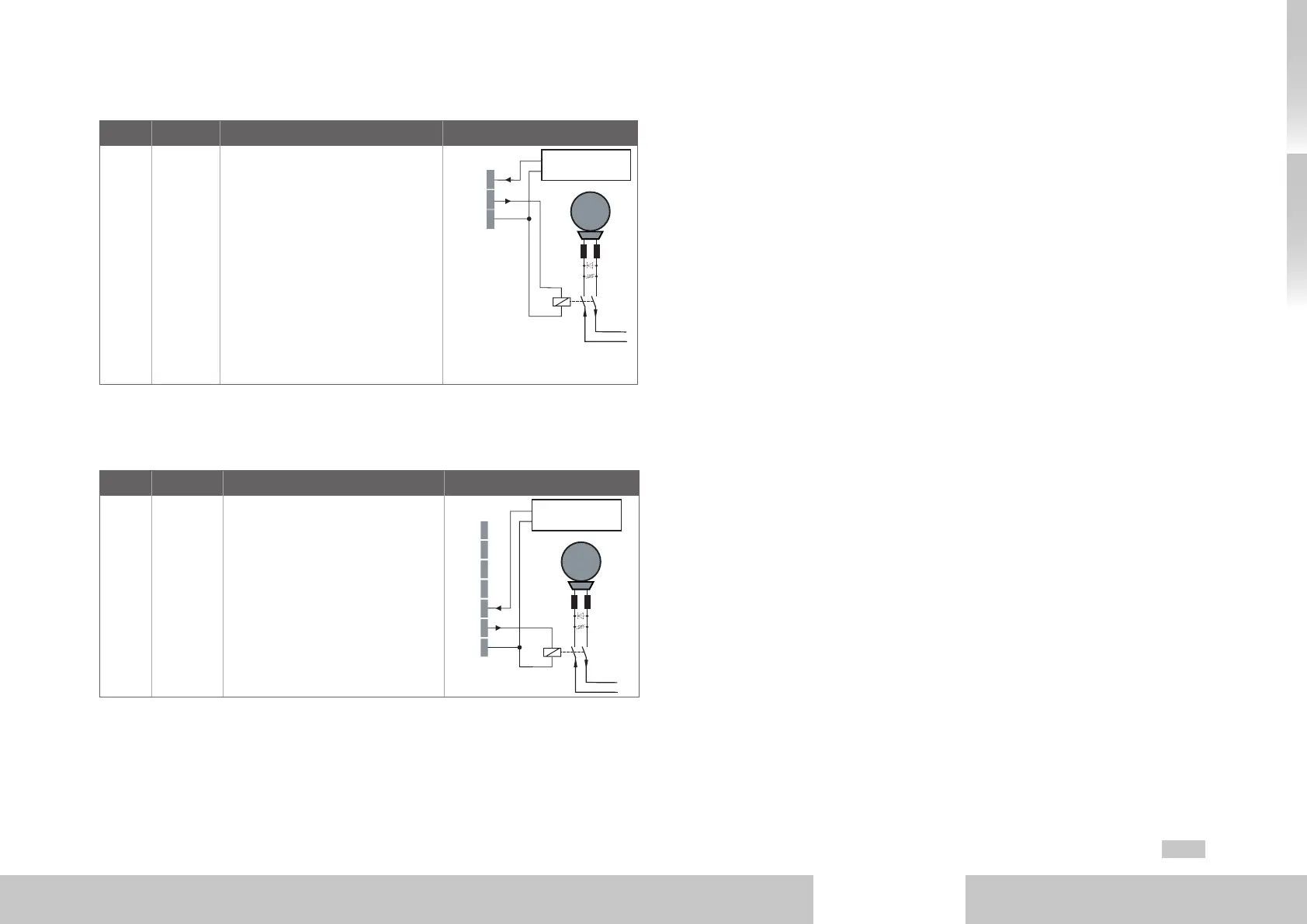
On Size5 to Size6A plug X20 serves the purpose of connecting a motor brake.
Des. Terminal Specification Connection
+24 V
OSD03
GND
X20/1
X20/2
X20/3
• Short-circuit proof
• External valtage supply
24VDC (I
IN
=2.1A) required
• To trigger a motor brake of up to
I
BR
=2.0Amaximum, for brakes
with higher current requirements a
relay must be connected in series.
• Overcurrent causes shut down
• Interruptible cable breakage
monitoring<200mAtypicallyin
condition "1" (up to relay)
X20
M
Brake (+)
Brake (-)
+24 V DC
+24 V DC 1
OSD03 2
GND 3
+24 V DC supply
for brake (I
IN
= 2.1 A)
Table 3.11 Specification of terminal connections X20 (Size5 to Size6A)
On Size7 plug X44 serves the purpose of connecting a motor brake.
Des. Terminal Specification Connection
+24 V
OSD03
GND
X44/5
X44/6
X44/7
• Short-circuit proof
• External valtage supply
24VDC (I
IN
=2.1A) required
• To trigger a motor brake of up to
I
BR
=2.0Amaximum, maximum,
for brakes with higher current
requirements a relay must be con-
nected in series.
• Overcurrent causes shut down
• Interruptible cable breakage
monitoring<200mAtypicallyin
condition "1" (up to relay).
X44
M
Brake (+)
Brake (-)
+24 V DC
+24 V DC supply
for brake (I
IN
= 2 A)
+24 V 1
GND 2
VL1 3
VL2 4
+24 V 5
OSD03 6
GND 7
Table 3.12 Specification of terminal connections X44 (Size7)
3.9 Specification USB interface
The service and diagnostics interface X2 has been realized as USB V1.1-interface. It is
solely intended for connecting a PC for commissioning, service and diagnostics with the
software Moog
DriveADministr Ator5.
Technical specification:
• USB1.1 standard - full speed device interface
• Connection via conventional USB-interface cable type A to type B
(see also MSDServoDrive Ordering Catalog)
3.10 Specification Ethernet interface
The service and diagnostics interface X3 has been realized as Ethernet interface. It is
solely intended for connecting a PC for commissioning, service and diagnostics with the
software Moog
DriveADministr Ator5.
Technical specification:
• Transfer rate 10/100MBits/s BASE-T
• Line protocol IEEE802.3 compliant
• Connection via conventional Crosslink cable
(see also MSDServoDriveOrdering Catalog)
3.11 Option 1
Depending on the MSDServoDriveAC-AC design variant, option 1 is provided with
various options ex-factory. Field bus options like e.g. EtherCAT or SERCOS are available.
All available options can be found in the MSDServoDriveOrdering Catalog. The user
manual for the respective option contains detailed information on commissioning.

 Loading...

