MSDServoDrive AC-AC Operation Manual
moog
35
Id. no.:CA65642-001 Date:03/2012
[
Installation
]
to the glossaryto the table of contents
3.13.3 Ready made-up encoder cables
The specifications can only be assured when using the Moog system cables.
CO8335
-
011
- yyy
Encoder cable
Ready made-up cable
Resolver cable
Encoder cable SSI, EnDat CA58876
Encoder cable Hiperface
® CA58877
002
002
Encoder system
Version
Cable length (m)
1) yyy stands for length in meters; standard length: 1 m, 5 m, 10 m, 15 m, 20 m, 50 m. Further length on request
Encoder cable CO8335-011-yyy
1)
Order code
Technical data encoder cable
Technical data C08335-011-yyy
1)
CA58876-002-yyy
1)
CA58877-002-yyy
1)
Motors with
encoder system
Resolver
G3, G5, G12.x
(single- / multi-turn
encoders with
SSI/EnDat interface)
G6, G6.x
(single- / multi-turn
encoder with
HIPERFACE
®
interface)
Assignment on
controller side
(Sub-D-plug)
1 = S2
2 = S4
3 = S1
4 = n.c.
5 = PTC+
6 = R1
7 = R2
8 = S3
9 = PTC-
1 = A-
2 = A+
3 = VCC (+5V)
4 = DATA+
5 = DATA-
6 = B-
8 = GND
11 = B+
12 = VCC (Sense)
13 = GND (Sense)
14 = CLK+
15 = CLK-
7, 9, 10 = n.c.
1 = REFCOS
2 = +COS
3 = U
S
7 – 12V
4 = Data+ EIA485
5 = Data- EIA485
6 = REFSIN
7 = Jumper to PIN12
8 = GND
11 = +SIN
12 = Jumper to PIN7
9, 10, 13, 14, 15 = n.c.
Capable for en-
ergy chains
yes
Minimum bending
radius
90mm 100mm 90mm
Table 3.14 Technical data encoder cable
Technical data C08335-011-yyy
1)
CA58876-002-yyy
1)
CA58877-002-yyy
1)
Temperature range
-40 ... +85°C
(-40 ... +185°F)
-35 ... +80°C
(-31 ... +176°F)
-40 ... +85°C
(-40 ... +185°F)
Cable diameter
approx.
8.8mm
Material of
oversheath
PUR
Resistance Resistant to oil, hydrolysis and microcic attack (VDE0472)
Certifications
UL-Style 20233, +80°C (+176°F)-300V,
CSA-C22.2N.210-M90, +75°C (+167°F)-300VFT1
Table 3.14 Technical data encoder cable
3.13.4 Resolver connection
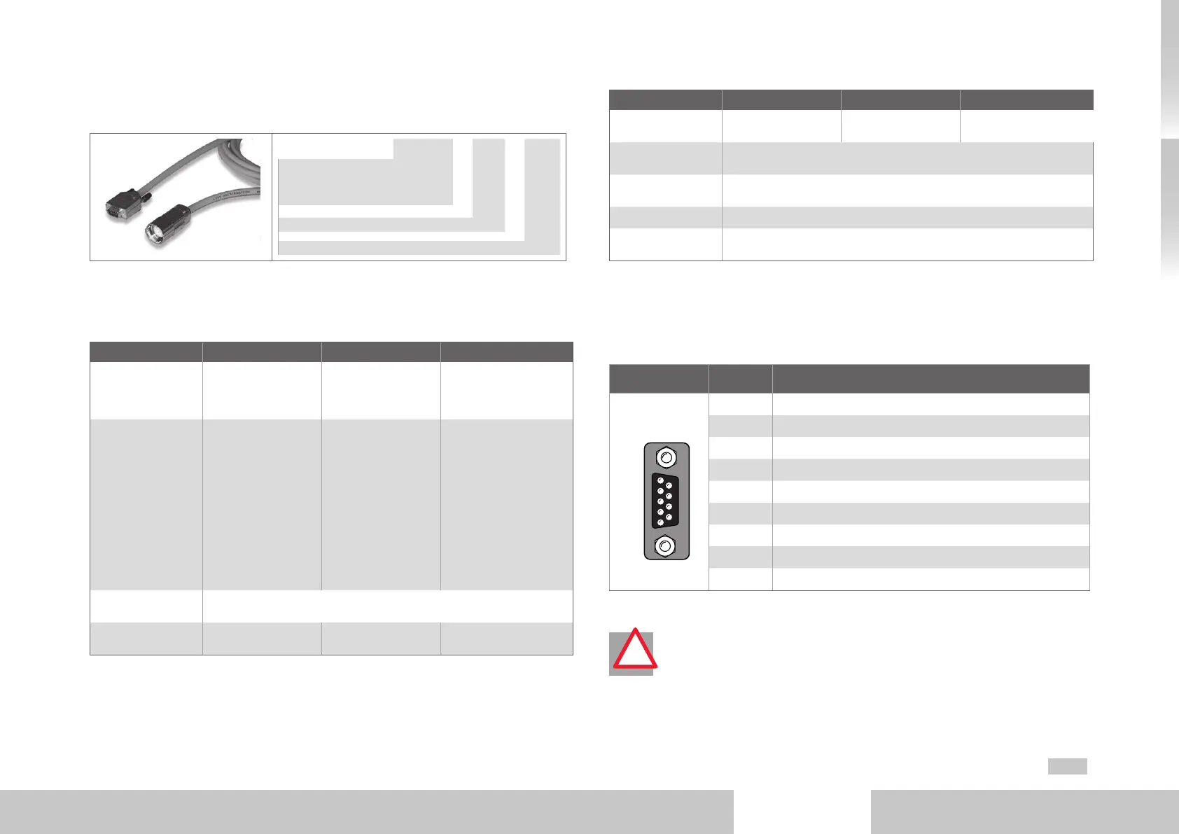
A resolver is connected to board slot X6 (9-pin D-Sub socket).
Fig. X6/Pin Function
5 4 3 2 1
9 8 7 6
X6
Resolver
1 Sin+ / (S2) analog differential input track A
2 REFSIN / (S4) analog differential input track A
3 Cos+ / (S1) analog differential input track B
4 Supply voltage 5..12V, internally connected with X7/3
5
ϑ+ (PTC, KT Y, Klixon)
2)
6 Ref+ analog excitation
7 Ref- analog excitation (ground reference point to pin 6)
8 REFCOS / (S3) analog differential input track B
9
ϑ- (PTC, K TY, Klixon)
2)
Table 3.15 Pin assignment X6
2)
ATTENTION! The motor’s PTC (also KTY and Klixon) must be designed with
reinforced insulation acc. to EN61800-5-1 against motor winding.
!

 Loading...

