8.3.
8.4.
8.5.
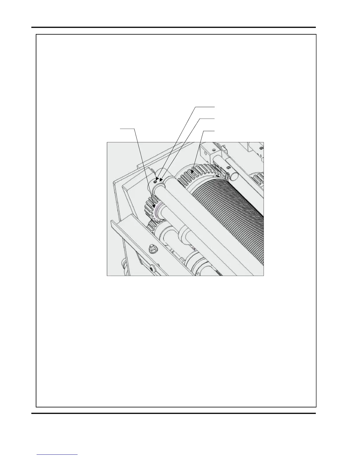
SwingthePerforatorbackupintoitsoperatingposition,setrollergap3tobealoose
pullonan80gsmstripandcheckthemeshbetweentheIdlerGearonthePerforator
Assembly&theDriveGearonthe3rd(Top)FoldRoller.
(removethe4securingscrewstoremovethecoverforbetteraccess)
ThegearmeshcanbeadjustedbyrotatingtheLaysideeccentricAdjusterCamafter
releasingitsM4lockingscrew.Checkthegearmeshthrough2fullrotationsofthe
PerforatorShaftstoensurenoeccentricityandlocktheCamintoposition.
RotatetheOperatorsideCamtoadjusttheparallelismoftheentireassembly&finally,
LocktheCamsintopositionwiththeirGrubScrews.
FIG.8.4
PerfDriveIdlerGear
LaysideAdjusterCam
FoldRollerDriveGear
M4LockingScrew