1-6 Computer Group Literature Center Web Site
Installation Procedures
1
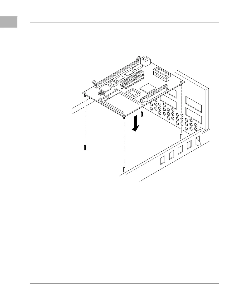
6. Insert four short Phillips screws through the holes at the corners of the
MBX board, into the standoffs you installed in the chassis, as shown
in the following illustration. Tighten the screws.
7. Connect the power and peripheral cables to the MBX board as
appropriate for your system configuration. (See MBX Connectors and
Pin Assignments on page 6-12 for pinout information and J7 IDE
Interface Configuration on page 6-9 for IDE related jumper settings.)
Note If you intend to use external battery backup instead of the on-
board battery backup, to avoid later loss of information in the
keep-alive circuits on the MBX board, we recommend that
you connect that external battery at the time you install the
MBX board. (See Connecting an External Battery on page
1-10.)
8. Connect the terminal that you plan to use as the EPPCBug system
console, if any, to the EIA-232-D serial port (J18 on the MBX board).
2155 9802

 Loading...


