Installing the Board
http://www.motorola.com/computer/literature 1-5
1
if it is unplugged.) The ESD strap must be secured to your wrist and to
ground throughout the procedure.
1. Perform an operating system shutdown. Turn the AC or DC power off
and remove the AC cord or DC power lines from the system. Remove
chassis or system cover(s) as necessary for access to the card cage.
2. Ensure that all jumper settings on the MBX board are configured as
appropriate for your application. (See MBX Jumper Headers on page
6-3.)
3. Attach any expansion modules you intend to use. (See Installing
Expansion Modules on page 1-7.)
Note Depending on your application, expansion modules can also
be attached with the MBX board already installed in your
system.
4. If the MBX board-to-chassis standoffs are not already installed in the
enclosure, insert the standoffs through the holes drilled for that
purpose in the chassis. Secure the standoffs with the nut driver or
screwdriver as appropriate.
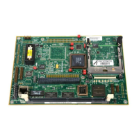
5. Place the MBX board on the standoffs.

 Loading...