4-6 Theory of Operation
Refer to Table 4-2 for the Tx/Rx OMAP SPI Module and Device Parameters.
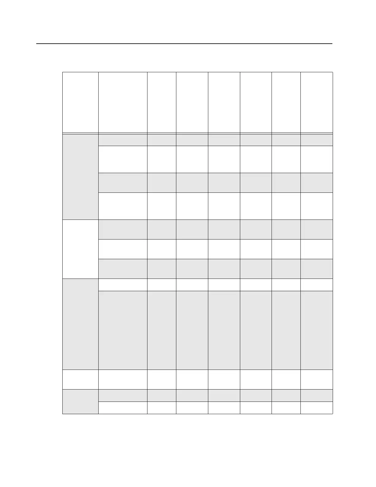
Table 4-2 Tx/Rx OMAP SPI Module and Device Parameters
Module SPI Device
Device
Enable
(active
high/
low)
MOSI
Data
Latched
(rising/
falling
edge of
SPI
clock)
Minimum
number
of bits
per
access
Max
Clock
Rate
Module
Select
active
to 1st
clock
edge
(min)
Data
complete
to
Module
select
negated
(min)
Exciter SPI CPLD High rising 8 bits 1 MHz – –
EEPROM
(Atmel
AT25640)
Low rising 32 bits
3
2 MHz 50 ns 50 ns
Trident IC Low rising 24 bits 20 MHz/
10 MHz
1
10 ns/
20 ns
1
0 ns
Metering ADC
(Maxim
Max149B)
Low rising 24 bits 1.8 MHz 100 ns 0 ns
PA
EEPROM
(AT25640)
Low rising 32 bits
3
2 MHz 50 ns 50 ns
DAC (Motorola
5183977M73)
Low rising 24 bits 500 kHz – 0 ns
ADC (TI
TLC542C)
Low rising 8 bits 1 MHz 3.8 us 0 ns
CNTL FPGA Low rising 16 bit 12 MHz – 0 ns
MAKO High rising 48 bit for
RTC
register
access
32 bit for
non-
RTC
register
access
10 MHz 11 ns 0 ns
WL MTR3000
Wireline FPGA
Low rising 8 bits 3.3 MHz – 0 ns
AUXIO MC74HC595A Low rising 8 bits 3.3 MHz – 0 ns
MC74HC598A Low rising 8 bits 3.3 MHz – 0 ns
 Loading...


