5-2 Troubleshooting
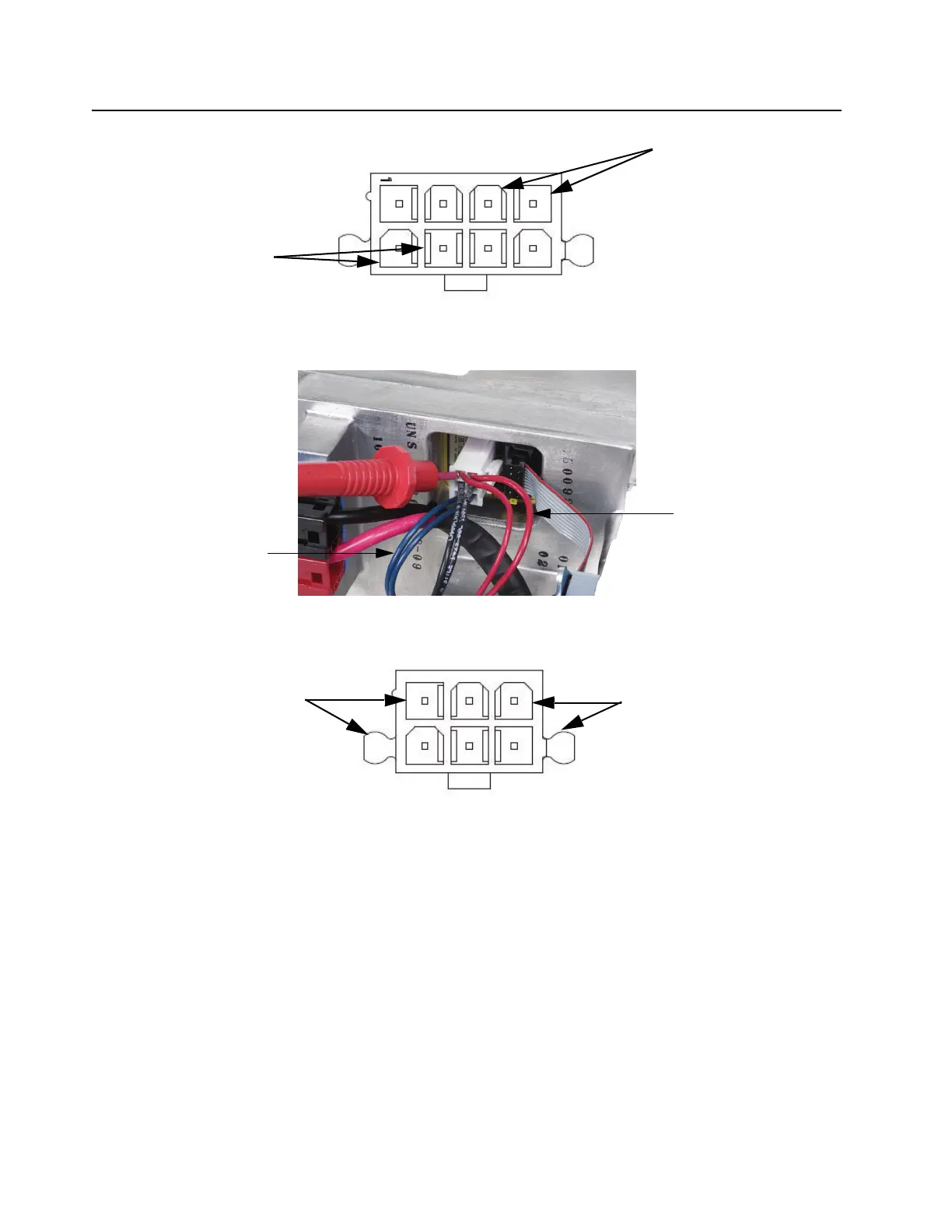
Figure 5-2 Pin-out of connector (measuring 14.2 VDC and 5.1 VDC)
To measure the 14.2 VDC and 28.6 VDC, refer to Figure 5-3 For the pin-out, refer to Figure 5-4
Figure 5-3 Measuring 14.2 VDC and 28.6 VDC (other voltmeter probe to chassis)
Figure 5-4 Pin-out of connector (measuring 14.2 VDC and 28.6 VDC)
If it is determined that the PSU is not functioning, the whole unit needs to be sent to the nearest
Motorola Repair Center to be replaced as it is not designed to be field serviceable.
1
4
1
4
5
8
1
4
3
6
28.6 VDC (either red wire)
14.2VDC (either blue wire)
14.2 VDC (blue wires)
28.6 VDC (red wires)
14.2 VDC (blue wires)
5.1 VDC (red-white wires)
 Loading...


