D-2 MOTOTRBO Base Station/Repeater – EME ASSESSMENT: Exposure Prediction Model
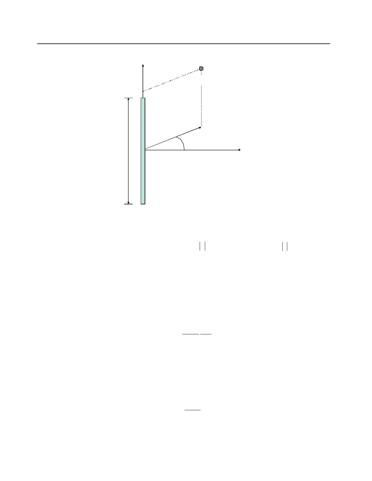
Figure D-1. Reference frame for the point of interest (POI) cylindrical co-ordinates
Per the reference frame in Figure D-1, the cylindrical-wave model is applicable in the volume
described in cylindrical co-ordinates ( ) as follows:
where is the wavelength in m, L is the antenna largest dimension in m, is the angle in
degrees defining the -3 dB beamwidth of a directional antenna (for an omni-directional antenna is
equal to 360 degrees), and
where is the antenna maximum gain relative to an isotropic antenna. The power flux density
( ), expressed in , is calculated as follows:
where is the input power to the antenna. In the region where,
the power flux density is calculated as the maximum between the cylindrical and spherical-wave
models, where the latter is expressed as follows:
Spatial power density averaging, which is required by some regulations, is embedded in the
cylindrical-wave model formulation, therefore it does not require additional considerations.
ρ
φ
z
POI
L
),,( z
,, z
λρλ
/2,min4/
2
Lr
c
≤≤
2/
δφ
≤
2/Lz ≤
,
,,
720/
LGr
Ac
A
G
S
2
/ mW
δρπ
180
L
P
S
cyl
=
(1)
λλ
/24/
2
Lr
c
≤≤
2
4
πρ
A
sph
PG
S =
(2)
 Loading...


