Installation
SUPREMATouch
137
US
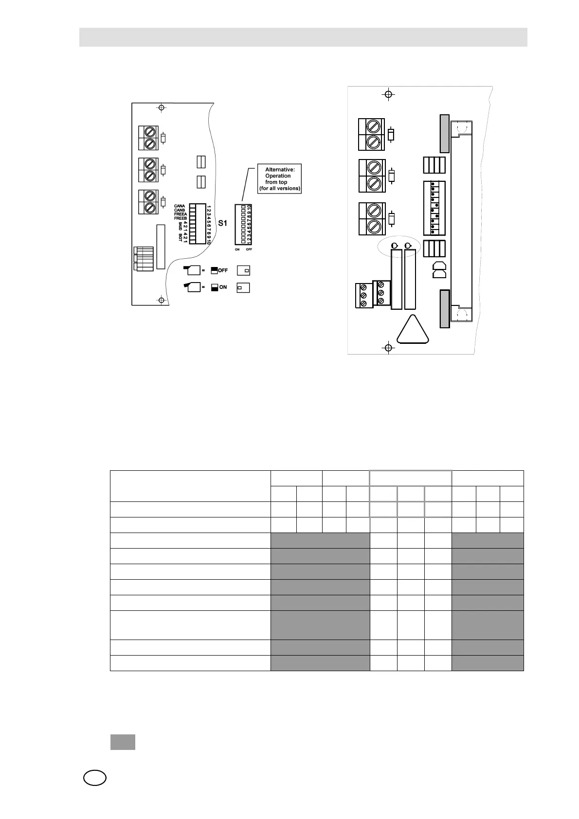
Fig. 64 MIB Module, DIL Switch (BGT = Rack No.)
CAN Bus Bit Rate Setting
The bit rates intended for the various expansion stages are listed in the following table.
Fig. 65 CAN BUS Bit Rate Settings/* MS = measuring point (input)
Explanation of the symbols
MIB as from layout version 2 has 2 system failure relays (X601) for SIL 3 applications.
CAN FREE Baud Rack
A B AB4 2 1 42 1
Switch No. 1 2 3 4 5 6 7 8 9 10
In the case of alternative assembly 10 9 8 7 6 5 4 3 2 1
Bit rate = 125 Kbit
ON ON ON
Bit rate = 10 Kbit ON ON OFF
Bit rate = 20 Kbit ON OFF ON
Bit rate = 50 Kbit ON OFF OFF
Bit rate = 125 Kbit OFF ON ON
Bit rate = 250 Kbit
Standard setting for up to 256 MS
OFF ON OFF
Bit rate = 500 Kbit OFF OFF ON
Bit rate = 1 Mbit OFF OFF OFF
= Any switch
c
1
a
EXT
INT
+
-
C
2
1
X
2
1
C
1
1
+
-
+
-
D
1
1
P
O
S
1
0
X 15
1
2
BAT
X
2
3
S
1
D
1
3
R
5
2
R
4
2
R
3
R
2
R
1
1
R
1
2
R
1
3
R
1
4
T1
T2
R
L
2
R
L
1
X601
D2
D1
X
2
2
O
N
3
4
5
6
7
8
9
1
2
1
1
1
0
D
1
2
1
1
0