SUPREMATouch
138
Installation
MSA
US
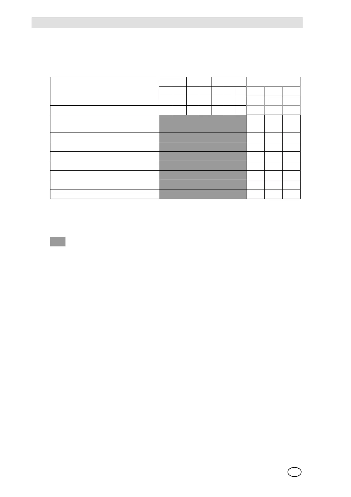
Rack-CAN Node Number (BGT No.)
In the following, the CAN node numbers to be set when several racks [BGTs] are being used are
listed. The standard setting for an individual rack is BGT 1.
Fig. 66 Rack -CAN Node Number
Explanation of the symbols
CAN-BUS Terminating Resistors
Both CAN bus systems (CAN-A + CAN-B) of the SUPREMA must have a terminating resistor at
each end of the bus. One end of the bus is located on the MDO module. A terminating resistor is
permanently connected here. For a 1-rack system, the other end of the bus is at the rear-panel
wiring of the MIB. If the system consists of only one rack, switches 1 and 2 of the DIL switch must
be set to the lower position.
If an additional rack is provided for the system, the racks are connected to each other at the rear
via the MST modules with ready-made CAN bus cables.
For a “multi-rack” system, the DIL switch contacts 1 and 2 (CAN-A, CAN-B) of the last rack – by
which the CAN BUS is ending - must be set to the lower position, all DIL switch contacts 1 and 2
(CAN-A, CAN-B) on the intermediate racks must be set to the upper position.
CAN FREE Baud Rack
A B AB4214 2 1
1 2 345678 9 10
In the case of alternative assembly 109 876543 2 1
BGT 1
Standard setting for a single rack (BGT)
ON ON ON
BGT 2
ON ON OFF
BGT 3
ON OFF ON
BGT 4
ON OFF OFF
BGT 5
OFF ON ON
BGT 6
OFF ON OFF
BGT 7
OFF OFF ON
BGT 8
OFF OFF OFF
= Any switch