Installation
SUPREMATouch
139
US
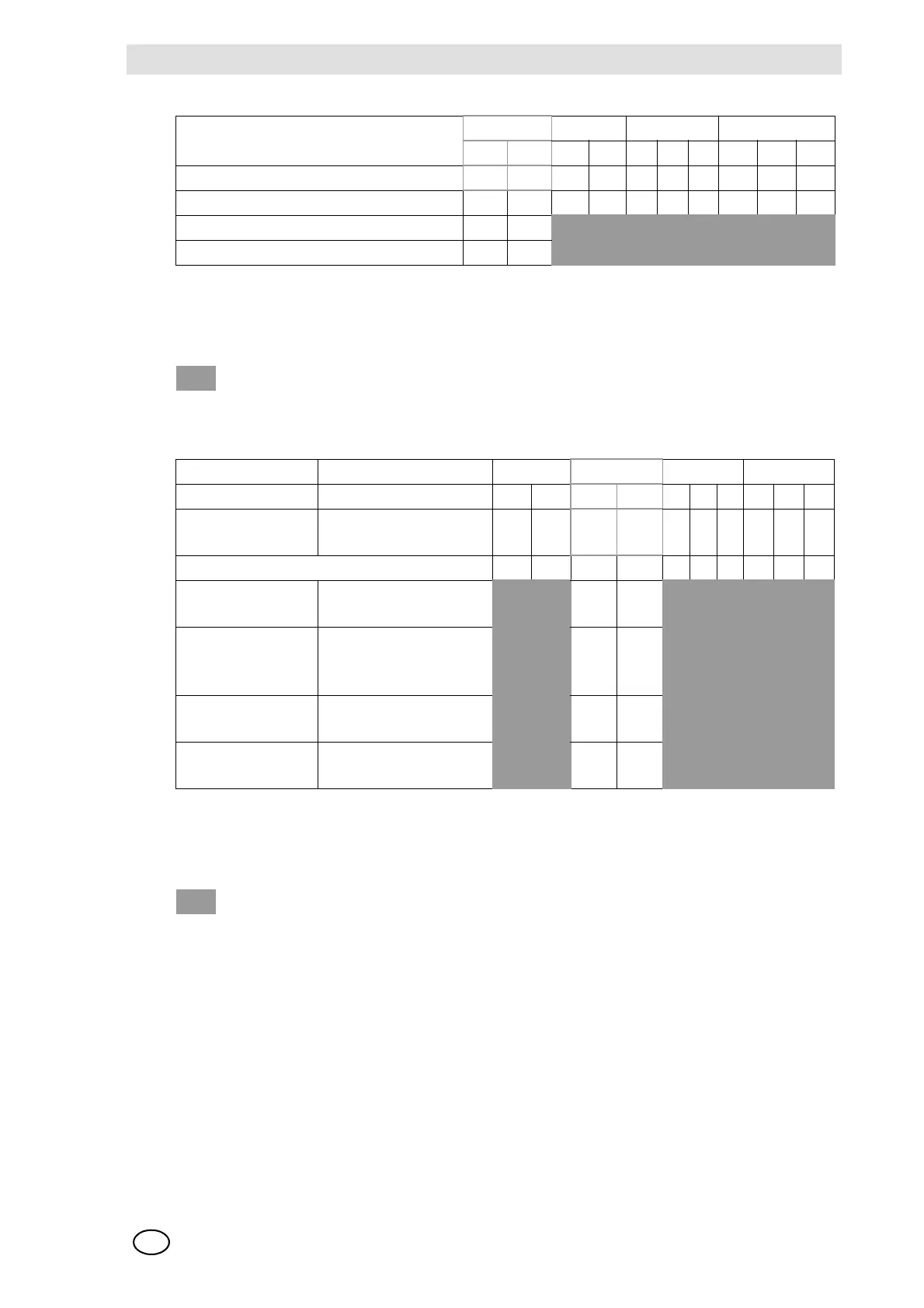
Fig. 67 CAN Bus Terminating Resistors
Explanation of the symbols
Turn-on Behaviour and Failure Behaviour of the MGO Module
Fig. 68 MGO Module, Configuration of turn-on behaviour and failure behaviour
Explanation of the symbols
CAN FREE Baud Rack
A B AB4214 2 1
Switch No. 1 2 3 4 5 6 7 8 9 10
In the case of alternative assembly 10 9 8 7 6 5 4 3 2 1
Terminating Resistor Closed (Standard) ON ON
Terminating Resistor Open OFF OFF
= Any switch
CAN FREE Baud Rack
ABAB421421
Turn-on behaviour Behaviour at CAN-Bus
failure
12345678910
In the case of alternative assembly 10 9 8 7 6 5 4 3 2 1
All relays remain
de-energised
All relays keep their last
state. (Standard)
ON ON
All relays remain
de-energised
After 72 h, all relays are
de-energised (accord-
ing SIL 3)
OFF ON
All relays are ener-
gised
All relays keep their last
state
ON OFF
All relays are ener-
gised
After 72 h, all relays are
energised.
OFF OFF
= Any switch