SUPREMATouch
140
Installation
MSA
US
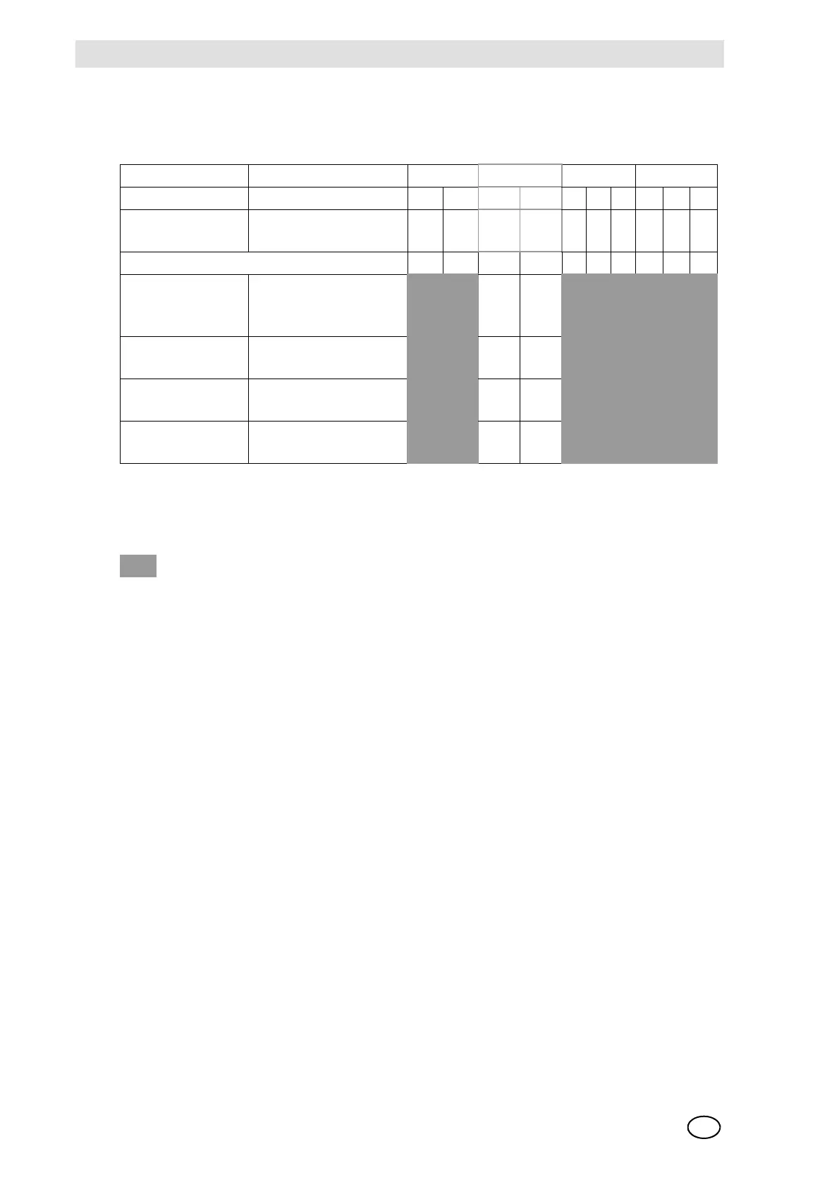
Turn-on Behaviour and Failure Behaviour of the MAO Module
During turn-on, at the analog outputs a 0 mA signal is issued.
Fig. 69 MAO Module, Configuration of turn-on behaviour and failure behaviour
Explanation of the symbols
Configuration of the MAI Module
Inserting the Adapter Modules (MCI/MPI/MFI/MSI)
For each input to which a sensor is to be connected, an input module (MCI/MPI) is inserted in the
MAI module. Up to 8 inputs can be connected to each MAI module. Essentially both active and
passive sensors can be connected. The module of the MCI type is provided for the connection of
active sensors, and the module of the MPI type is used for the connection of passive sensors.
The MFI module has been provided for the connection of manual or automatic fire detectors. The
MSI module has been provided for the connection of external switches.
The terminal posts on the (MAT module and MAT TS module) are designed for the connection of
conductors with a cross section in the range of 0.2 ... 1.5 mm.
NOTE: During installation, it is essential to verify for each input that the type of adapter module
provided for the sensor is plugged into the correct slot on the MAI module (Chapter 10.3)
CAN FREE Baud Rack
ABA B 421421
Turn-on behaviour Behaviour at CAN-Bus
failure
123 4 5678910
In the case of alternative assembly 10 9 8 7 6 5 4 3 2 1
All analog outputs
are 0 mA.
All analog outputs keep
there last state. (Stand-
ard)
ON ON
All analog outputs
are 2 mA.
All analog outputs keep
there last state.
OFF ON
All analog outputs
are 0 mA.
After ca. 2 min all along
outputs are 0 mA.
ON OFF
All analog outputs
are 2 mA.
After ca. 2 min all along
outputs are 0 mA.
OFF OFF
= Any switch