Installation
SUPREMATouch
145
US
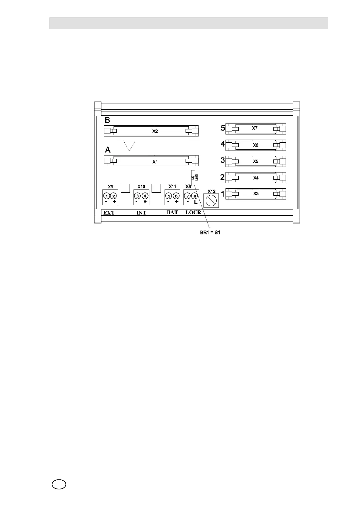
Configuration of the MRC TS Module
A solder bridge (BR1), which is used to determine the function of the relay inhibit (Chapter 10.7)
for the connected relay modules, is provided on the module:
Solder bridge BR1 = OPEN = relays are energised when the relay inhibit is turned on
Solder bridge BR1 = CLOSED = relays are de-energised when the relay inhibit is turned on
Fig. 75 Configuration of the MRC TS Module
NOTE: Because the common alarms are normally energised and this is fixed in the system and
cannot be changed, solder bridge BR1 on the first MRC TS module in the system (the first 40 relay
outputs) should never be closed (unless an alarm is to be triggered when the relays are inhibited).
In addition, the first 32 available relay outputs
(relay output 9-40; 1st MGO module in the system) should also be configured according as nor-
mally energised, like the common alarms, when the option of inhibiting the relays via the LOCK
connection is used.
Configuration of the MRO 8 TS Module
The function of the relay inhibit is determined by solder bridge BR1 on the MRC TS module.
Configuration of the MRO 16 TS Module
The function of the relay inhibit is determined by solder bridge BR1 on the MRC TS module.
Configuration of the MUT Module
No configuration
Configuration of the MAR Module
No configuration
Configuration of the MST Module
No configuration