SUPREMATouch
144
Installation
MSA
US
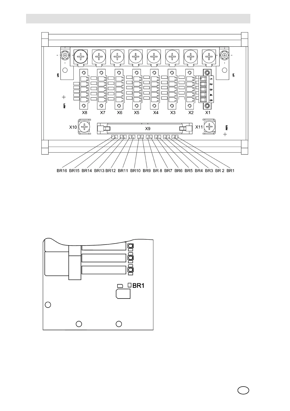
Fig. 73 Configuration of the MAT TS Module
Configuration of the MRO 8 Module
On the module, there is a solder bridge (BR1), which is used to define the function of the relay
inhibit of the common alarms (Chapter 10.10) is established:
Solder bridge BR1 = OPEN = relays are energised when the relay inhibit is turned on
Solder bridge BR1 = CLOSED = relays are de-energised when the relay inhibit is turned on
Fig. 74 Configuration of the MRO 8 Module
NOTE: Because the common alarms are normally energised and this is fixed in the system and
cannot be changed, solder bridge BR1 should never be closed under any circumstances (unless
an alarm is to be triggered when the relays are inhibited).