Installation
SUPREMATouch
187
US
Fig. 121 MRO Module, Contact Load Capacity
NOTE: For the safety related use of each relay, the alarm and failure relays of the SUPREMA sys-
tem has to be used in the following condition:
1.Relay under power
2.Alarm or fault contact is closed
Thereby it will be assured that the relay contacts will give a failsafe signal at power fail or line dis-
connection
NOTE: To ensure a save relay contact operation the relay output must be fused to get a overload
protection. To calculate the fuse rating, multiply the maximal allowed nominal current by factor 0.6.
MRO 8 Module Relay Output Unit Common Alarms
This module is used only when relays are required for common alarms and installation is to be
done directly on the rack. The module offers 8 common alarm relays and can be plugged directly
into the rear of the rack. Each relay has a changeover contact, which is connected to terminals.
The common alarm relays can be inhibited by connecting a switch to the LOCR contact of the MST
module (see section 2.10.7). As standard practice, the common alarm relays are normally ener-
gised (i.e. a relay is energised – no alarm. The relay is de-energised when an alarm is triggered
at one or more inputs.).
NOTE: The MRO 8 module must be installed in POS 9 only! It is impossible to be use more than
one MRO 8 module in one rack.
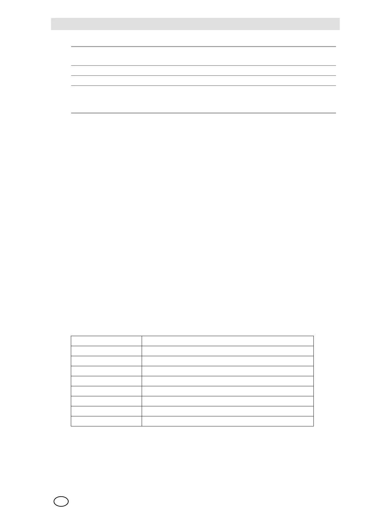
Fig. 122 MRO 8 Module, Relay Assignment
Maximum Switching Voltage 400 VAC
300 VDC
Maximum Switching Power, ac: 1500 VA
Nominal Current 3 ADC
Maximum Switching Power, dc:
(from the load limit curve)
24 VDC/3 A
50 VDC/0.3 A
100 VDC/0.1 A
Relay No. Assignment
11
st
Alarm
22
nd
Alarm
33
rd
Alarm
44
th
Alarm
5 Signal Failure (Sensor)
6Horn
7 Inhibit
8 Power Supply Failure