SUPREMA
230
Connection of Peripherals
MSA
US
Truth Table
For the status register from address 10001 on, the following truth table (10001–10008) is valid for
measure point MS 1 (at version 1.02.07 and PKV Firmware 1.101).
For measure points MS 2–56 see above as for measure point MS 1.
Setting the CANopen node address:
For the gateways, the CANopen node numbers
124 = HEX 7C, switch 1 to C, switch 16 to 7
125 = HEX 7D, switch 1 to D, switch 16 to 7
provided on the PKV 30 (see also fig. 169).
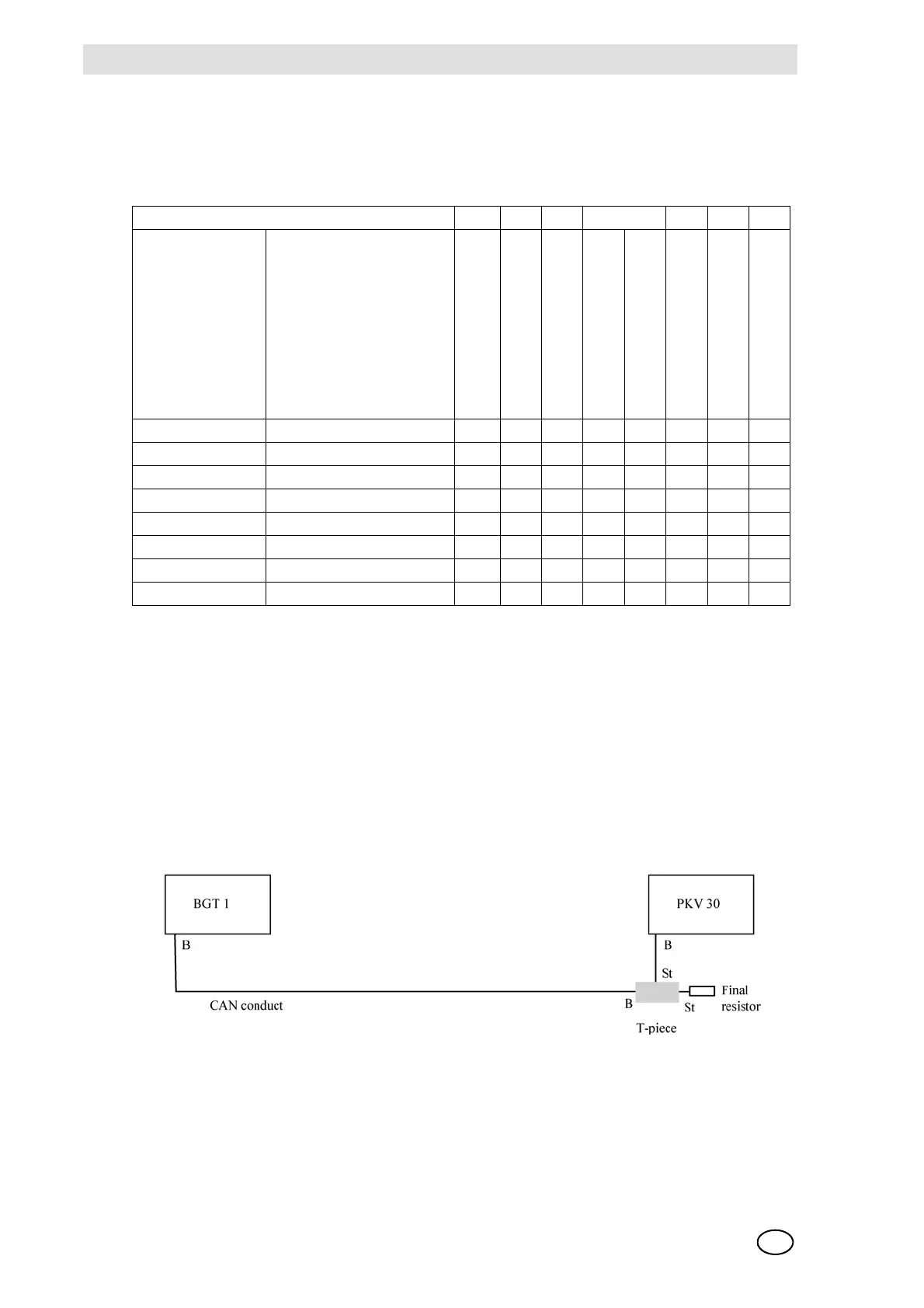
Connection to the SUPREMA:
Fig. 168 Connection Suprema Gateway CAN/Modbus RTU
The CAN terminating resistor of rack 1 has not been set, therefore at the T-piece of the PKV 30 a
terminating resistor is connected.
Event
Memory address Data value
1
st
alarm
2
nd
alarm
3
rd
alarm
4
th
alarm
Calibration
Signal failure
Inhibitet
Measure range exceeded
10001 1st alarm 1 0000001
10002 2nd alarm 0 1000001
10003 3rd alarm 0 0100001
10004 4th alarm 0 0010001
10005 Calibration 0 0001000
10006 Signal failure 0 0000100
10007 Inhibited 0 0000010
10008 Measure range exceeded0 0000001