SUPREMA
238
Redundant Systems
MSA
US
NOTE: The layout of the circuit connected to the MRO 8 TS resp. MRO 16 TS modules depends
on the requirements of the respective application. It is completely up to the users responsibility to
observe the valid standards and guidelines.
NOTE: The MRO 16 TS modules do not have changeover contacts. The working contacts of the
redundant relays are connected in series. (1 or 2 contacts open = alarm). Two terminal blocks with
screw terminals are used to connect to the relay contacts.
Installation MGO Module
Before plugging in modules, the SUPREMA system must be voltage-free.
The module must be configured via jumper plugs for the CAN B bus.
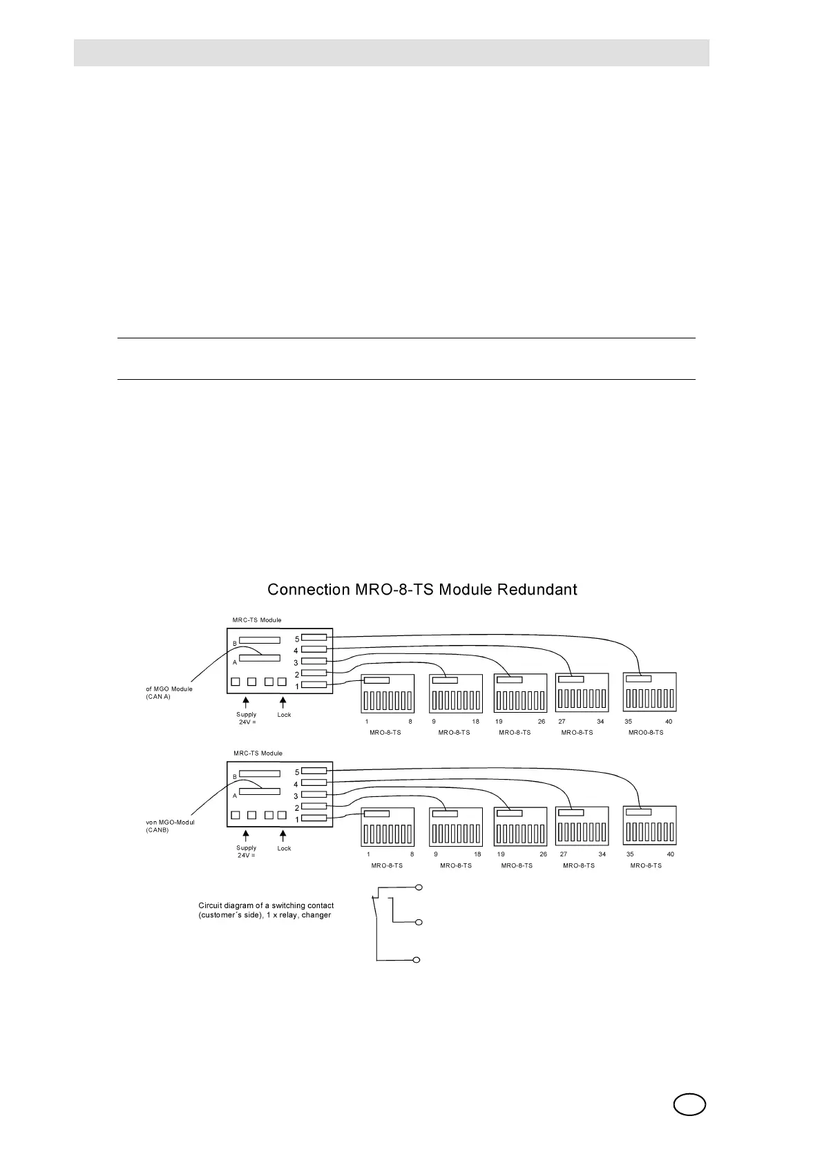
Connection MRO 8 TS Module
On redundant systems, the outputs of 2 MGO modules must always be connected
(channel A + B).
The 40 driver outputs of the MGO modules are connected to the MRC TS modules of Plug A using
a 40-way ribbon cable via MUT modules at the rear of the rack. Plug B is only used if MRO 16 TS
modules are connected. Using a 20-way ribbon cable each of the plugs 1–5 are connected to the
8 driver outputs of the MGO module to up to 5 MRO 8 TS modules.
Fig. 176 Connection MRO 8 TS Redundant Module
The terminal connections and the relay assignment of the MRO 8 TS module are described in de-
tail in chapter 10.7.
CAN-A BR11 + BR13 = CLOSED & BR12 + BR14 = OPEN
CAN-B BR11 + BR13 = OPEN & BR12 + BR14 = CLOSED