SUPREMA Sensor Data Sheets
SUPREMA
295
US
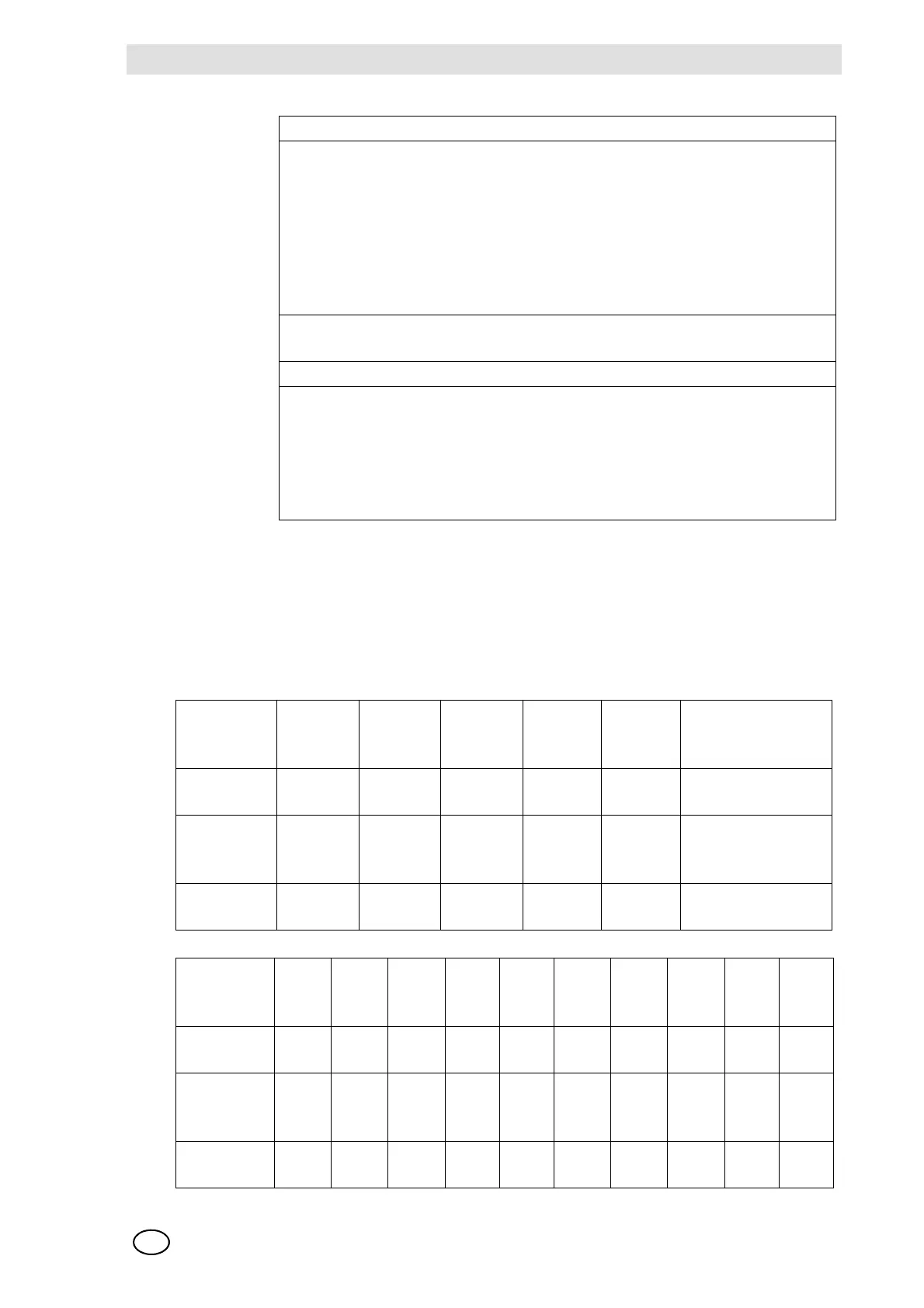
Startup: Presetting required —> before first calibration and when changing sensor
Presetting: Connect digital voltmeter to MAI card jacks.
Bridge current setting —> 280 mA
Zero adjustment by zero gas —> Zero setting to Ua = 400 … 450 mV
Sensitivity adjustment with measuring gas -> Measuring range level
Ua = 1950 ... 2100 mV or by means of the value of the existing gas concentration
according to: Ua (mV) = C (Span gas concentration in % of measuring range)/
100 * 1600 + 400
Warm-up
period:
15 min minutes for presetting,
2 hours for calibration
Function test: Span gas application via: test cap with 1,0 l/ min (Order-No.: 10049316)
Calibration: Calibration procedure according to SUPREMA operation manual
For measuring components allowed, measuring ranges, lower alarm levels and
conditions for calibration see list of components (Order-No.: D0792420)
Possible other measuring components and measuring ranges on request.
Open or Short Circuit Fault Indication:
X= Signal failure (FAIL-LED)
XX= Alarm LED‘s, Signal exceeded, Signal failure (FAIL-LED)
XXX= only alarms
XXXX= no change of indication
Open-circuit
at the MAT
(TS) Module
Wire
-X1/1
Wire
-X1/2
Wire
-X1/3
Wire
-X1/4
Wire
-X1/5
Disconnect plug of
MAT (TS)
Failure
indication
XXX X XXX
Open-circuit
at max. cable
length
Wire
-X1/1
Wire
-X1/2
Wire
-X1/3
Wire
-X1/4
Wire
-X1/5
Disconnect plug of
MAT (TS)
Failure
indication
XXX X XXX
Short-circuit
at the MAT
(TS) Module
Wire
-X1/1/-
X1/2
Wire
-X1/1/-
X1/3
Wire
-X1/1/-
X1/4
Wire
-X1/1/-
X1/5
Wire
-X1/2/-
X1/3
Wire
-X1/2/-
X1/4
Wire
-X1/2/-
X1/5
Wire
-X1/3/-
X1/4
Wire
-X1/3/-
X1/5
Wire
-X1/4/-
X1/5
Failure
indication
X XXX X XXXXX X X XX
Short-circuit
at max. cable
length
Wire
-X1/1/-
X1/2
Wire
-X1/1/-
X1/3
Wire
-X1/1/-
X1/4
Wire
-X1/1/-
X1/5
Wire
-X1/2/-
X1/3
Wire
-X1/2/-
X1/4
Wire
-X1/2/-
X1/5
Wire
-X1/3/-
X1/4
Wire
-X1/3/-
X1/5
Wire
-X1/4/-
X1/5
Failure
indication
XXXX XX X X XX XX X X X XXXX