HYDROCAL 1005 Manual for Installation and Operation Page 4/111
1. General
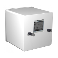
The HYDROCAL 1005 is a permanently-installed multi-gas-in-oil analysis system with transformer
monitoring functions. It allows for the individual measurement of moisture and the key gases hydro-
gen (H
2
), carbon monoxide (CO), acetylene (C
2
H
2
) and ethylene (C
2
H
4
) dissolved in transformer oil.
As hydrogen (H
2
) is involved in nearly every fault of the isolation system of power transformers and
carbon monoxide (CO) is a sign of an involvement of the cellulosic / paper isolation the presence and
increase of acetylene (C
2
H
2
) and ethylene (C
2
H
4
) further classifies the nature of a fault as overheat-
ing, partial discharge or high energy arcing. The device can serve as a compact transformer monitor-
ing system by the integration / connection of other sensors present on a transformer via its analog
inputs:
5 analog outputs 0/4-20mADC
4 analog inputs 0/4-20 mADC (Option)
6 analog inputs 0/4-20 mADC +20% / 0-80 VAC +20% (option)
configurable by jumpers
It is further equipped with digital outputs for the transmission of alarms or the execution of control
functions (e. g. control of a cooling system of a transformer):
5 digital relay outputs
5 digital opto-coupler outputs (Option)
Key Advantages
Hydrogen (H
2
), Carbon monoxide (CO), acetylene (C
2
H
2
) and ethylene (C
2
H
4
) measurement
Moisture-in-oil measurement
Communication interfaces ETHERNET 10/100 Mbit/s (copper-wired or fibre-optical) and RS 485
to support proprietary communication protocols and to be open / prepared for substation commu-
nication protocols IEC 61850, MODBUS, DNP 3 etc.
Optional on-board GSM and analog modems for remote communication
6 analog AC current inputs for the connection of capacitive HV bushing sensors for HV bushing
monitoring applications
The present operating instructions are divided in the following sections:
Instructions for mounting the HYDROCAL 1005 unit (chapter 2)
Hardware components of HYDROCAL 1005 (chapter 3)
Description of software of the HYDROCAL 1005 unit (chapter 4)
Description of Windows software HydroSoft (chapter 5)
RS 485 Wiring (chapter 6)
New HydroSoft Scheduler functions (chapter 7)
Technical Data of HYDROCAL 1005 (chapter 8)
HYDROCAL 1005 dimensional drawings (chapter 9)