HYDROCAL 1005 Manual for Installation and Operation Page 86/111
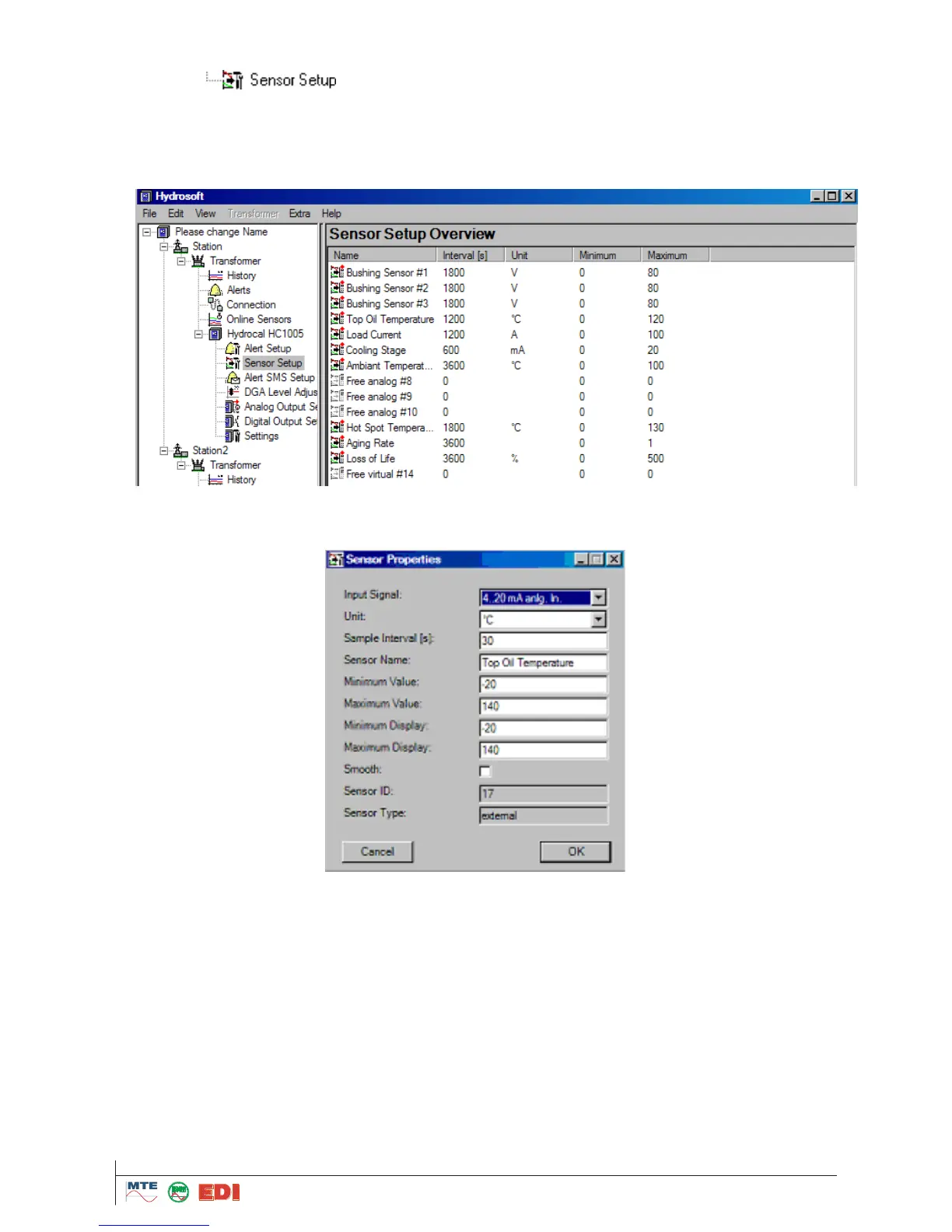
5.10.2 External sensors (see also chapter 4.7.3)
In the menu , the settings of external sensors are modified. The form of presenta-
tion can be chosen as under alarms as
„List“
„Symbol“
„Details“
The menu „Sensor properties“ is opened by double clicking on a value or a symbol. The settings of
internal sensors cannot be modified and are therefore greyed out.
In the box „Input Signal“, the unit of the input signal can be selected. For the first six inputs (Free
analog #1 to Free analog #6), according to options purchased, the following must be chosen:
With option Bushing input: ”0...20mA AC Bush. In.“ or “0...100V AC Bush. In.“
With option Current input (External Sensors): “0...20mA anal In“ or “4...20mA anal. In“
For the next four inputs (Free analog #7 to Free analog #10), according to options purchased, the
following must be chosen:
With option Current input (External Sensors): “0...20mA anal In“ or “4...20mA anal. In“
For the next four inputs (Free virtual #11 to Free virtual #14), these four inputs are virtual sensors
and in any case have to be consider as external sensors or bushing sensors. It is used for calcula-
tion of Hot Spot Temperature, Aging Rate and Loss of Life