HYDROCAL 1005 Manual for Installation and Operation Page 8/111
2.3 Preparation for installation
Before installation, a visual inspection of the unit must be carried out. Remove the protection cover
and check visually the components. All cables and tubes must be connected.
2.3.1 Power supply for the unit
The HYDROCAL1005 unit requires an auxiliary power supply of 110 / 230V close to the unit. The
power needed is max. 350 VA.
2.3.2 Requested tools:
Long Allen key, size 4 for aeration screw
Bucket, oil absorber, cleaning rag
Teflon-band
Drill / screw driver
Digital multimeter
Tin spanner M55 or adjustable tin spanner of 1 ½“ for valve and fittings
To seal the thread of the measuring head, either Teflon band (minimum 4 to 5 layers must be ap-
plied) or an O-Ring must be used.
2.4 Installation of the HYDROCAL1005 unit
Please mount the HYDROCAL1005 unit on a valve with full opening (full bore valve) or a ball valve
with an internal thread of 1½” (DIN ISO 228: G 1½) . The HYDROCAL unit has a 1½’’ thread (Di-
mensional drawings, see. chapter 8). As an option a valve with NPT 1½ standard can also be used.
A good oil flux should exist on the mounting location. If necessary, use a reduction piece (adapter).
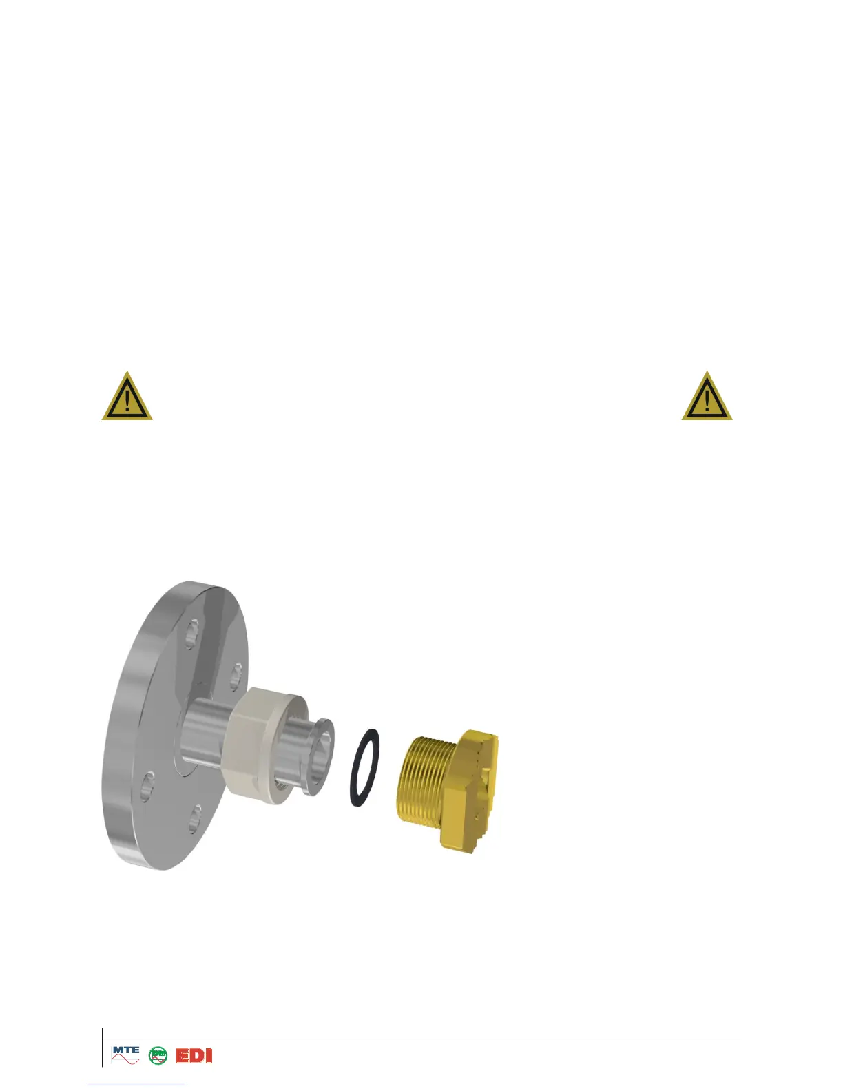
It is recommended to mount the HYDROCAL 1005 unit to valve with a union- or sleeve nut. In this
case the device has not to be turned to fix during the installation. An O-ring should be used as seal-
ing.
In case there exist strong vibrations on the mounting valve, the valve should be relieved by a sup-
port.
Then mount the unit according to the following steps: