Transducer Connections
Model 493.02 Controller Service
Sensors
83
Transducer Connections
Transducer connections require a conditioner daughter board be
installed in the I/O Carrier module. The following conditioners can be
installed:
• Model 493.25 Digital Universal Conditioner
• Model 493.47 Encoder
• Model 493.48 Acceleration Conditioner
Each Model 493.40 I/O Carrier module can include up to four daughter
boards. Each installed daughter board is assigned a specific I/O Carrier
module front panel connector (J4–J7 I/O). These connections can be
used for any type of sensor (provided the appropriate daughter board
is installed).
A hardware interface file (.hwi) defines each type of module (and their
associated daughter boards) and maps each module location for the
system software. The .hwi file and the physical locations for each type
of module and associated daughter boards must match.
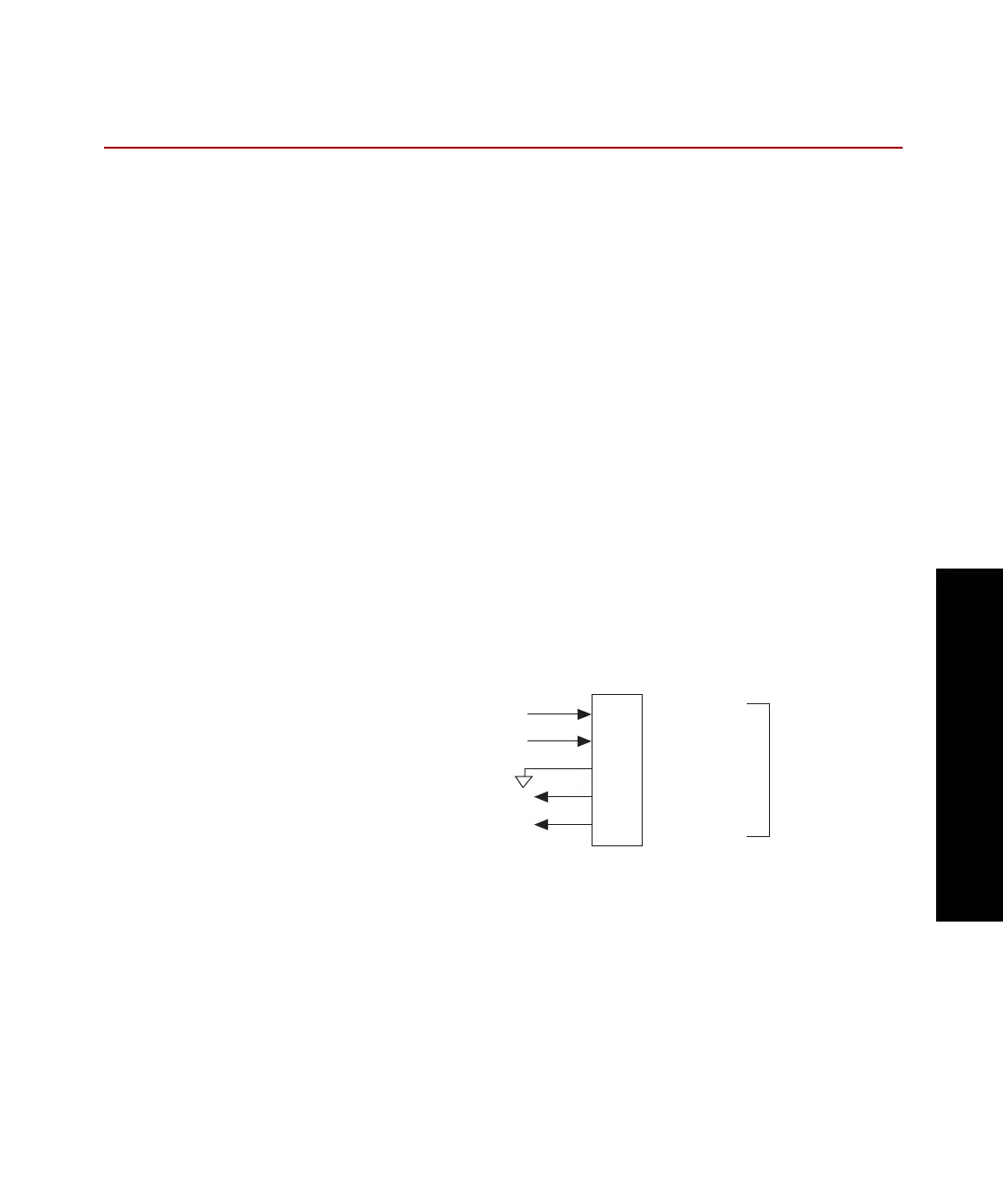
Excitation and
feedback signals
are passed
through to the
transducer.
J4 - J7
To/From
Conditioner
To/From
Transducer
1
2
3
4
5
+ Excitation
- Excitation
Guard
+ Feedback
- Feedback
 Loading...