Model 493.02 Controller Service
Shunt Calibration
Sensors
92
Shunt Calibration/Bridge Completion
On a typical system, shunt calibration and bridge completion resistor
installation is completed on the I/O Carrier module.
If you have purchased optional sensor cables with transducer ID
modules, shunt calibration and bridge resistors are installed on these
modules.
I/O Carrier Module
Shunt calibration
connector
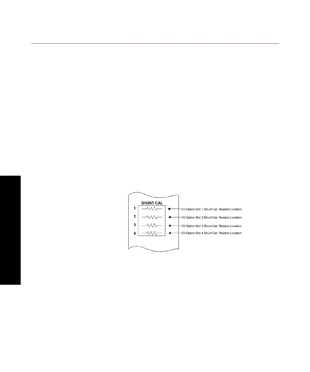
The I/O Carrier module has a shunt calibration connector on its front
panel that allows up to four shunt resistors (1 per slot) to be plugged
in. The SHUNT CAL connector is labeled to indicate which slot the
shunt calibration resistor is tied to.
Each shunt calibration resistor is soldered to a 2-pin holder (MTS part
number 114338-26). This holder plugs into the front panel connector
shown below. Refer to the 493.40/41 Carrier I/O Shunt Calibration Kit
(MTS part number 100-028-185) for more detailed information on kit
components and installation.
 Loading...