Shunt Calibration
Model 493.02 Controller Service
Sensors
91
7. Install the shunt calibration resistor as follows:
A. Select the appropriate shunt calibration resistor.
B. Bend the resistor leads 90º for a 0.3 inch separation.
C. Cut the resistor leads 0.12 inch from the bend.
D. Insert the resistor into the connector solder cups and solder.
E. Complete and attach a shunt calibration label as specified on
the 493.40/41 Carrier I/O Shunt Calibration Kit (MTS PN 100-
028-185).
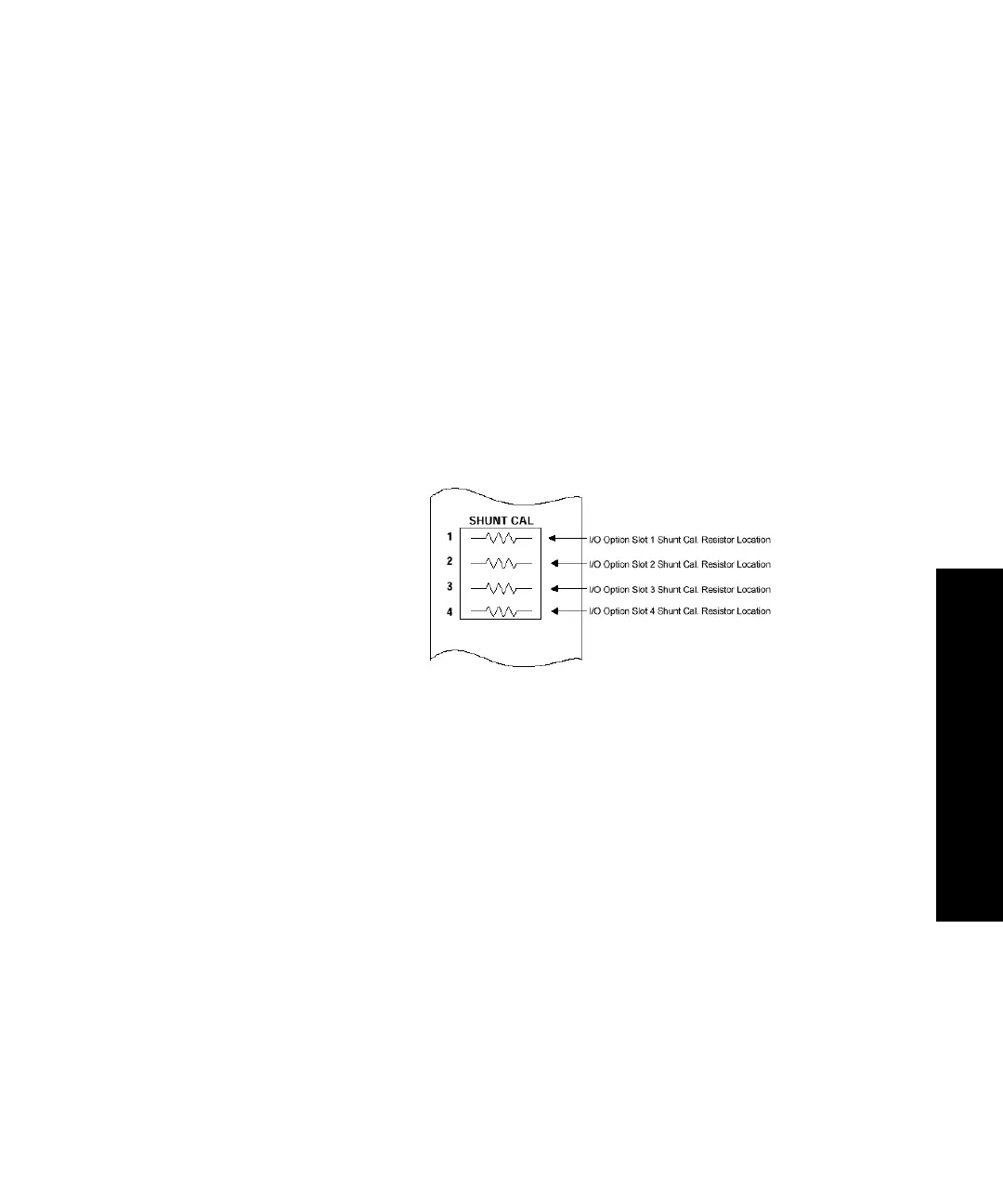
F. Install the shunt calibration resistor/connector assembly into
the appropriate SHUNT CAL connector slot on the front
panel of the appropriate I/O Carrier Module.
8. Verify that force is still zero.
While it is unlikely, it is possible for the force signal to change
when the control mode changes. If it does, select Auto Offset to
zero the force output.
9. Perform a shunt calibration.
Refer to “How to Perform a Shunt Calibration” in Chapter 2,
Common Tasks of the FlexTest SE User’s manual for a detailed
procedure.
 Loading...