Technical Manual N5 (CANopen)
3 Technical details and pin assignment
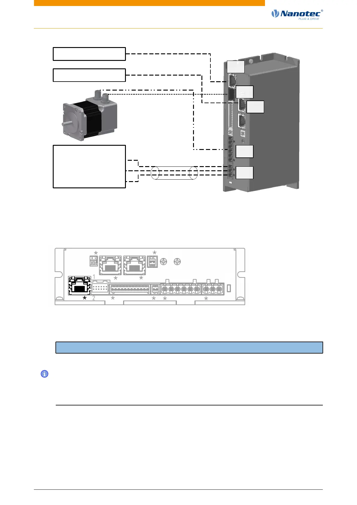
shielding (optional)
Encoder
X6
X5
X2
X3
X1
Power (Motor)
GND
+Ub
Power supply
Ethernet
CANopen Master
3.6.2 Connector X1 – Ethernet
Pin 1 is marked with an asterisk "*".
X7
X5X1 X2 X3 X4 X6
L1
X6
S1
X8X9S3
S2
3.6.3 Connector X2 – encoder/Hall sensor
Note
Two types of encoder/Hall sensor are supported:
1. Encoder/Hall sensor with 5 V supply voltage. In this case, nothing is to be connected to connector
X7; object 2059
h
must be set to the value "0" (factory setting).
2. Encoder/Hall sensor with 24 V supply voltage. In this case, you must connect a voltage of 24 V
DC to connector X7 (see Connector X7 – voltage supply for encoder/Hall sensor, external
logic supply) and set object 2059
h
to the value "1".
Pin 1 and pin 2 are marked in the figure.
Version: 2.0.1 / FIR-v1650 20


 To Next Page