Technical Manual N5 (CANopen)
6 Operating modes
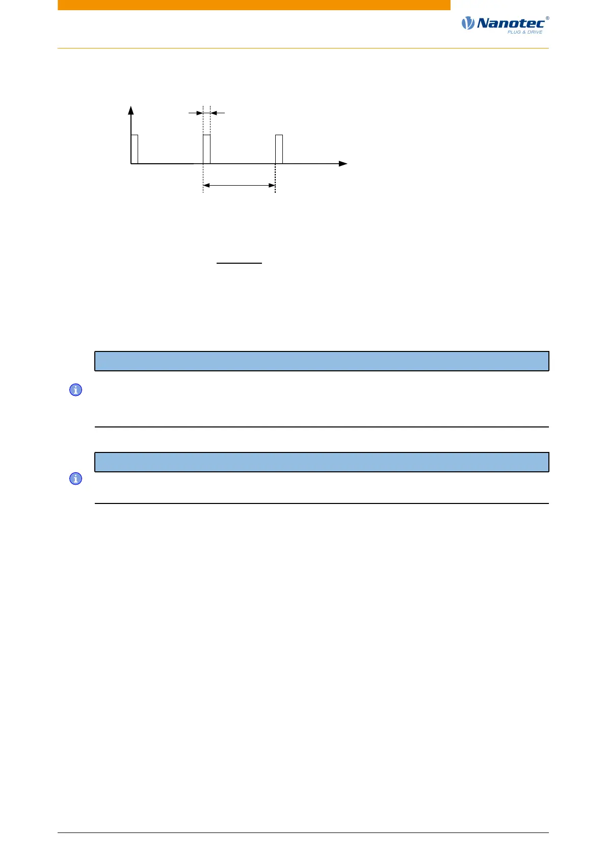
t
min. 1µs
(max. 1MHz)
min.
200ns
clock
input
• The steps are scaled using objects 2057
h
and 2058
h
. The following formula applies here:
step width per pulse =
2057
h
2058
h
The "step size per pulse" value is set to 128 (2057
h
=128 and 2058
h
=1) ex works, which
corresponds to a quarter step per pulse. A full step is the value "512", a half step per pulse
corresponds to "256", etc.
Note
For a stepper motor with 50 pole pairs, 200 full steps correspond to one mechanical revolution of
the motor shaft.
In clock-direction mode, the BLDC motors are also handled as stepper motors by the controller. This
means that for a BLDC motor with, e.g., 3 pole pairs, 12 (=4*3) full steps correspond to one revolution.
Note
If there is a change of direction, a time of at least 35 µs must elapse before the new clock signal
is applied.
6.10.4 Statusword
The following bits in object 6041
h
(statusword) have a special function:
• Bit 13 (Following Error): This bit is set in closed loop mode if the following error is greater than the
set limits (6065
h
(Following Error Window) and 6066
h
(Following Error Time Out)).
6.10.5 Subtypes of the clock-direction mode
Clock-direction mode (TR mode)
To activate the mode, object 205B
h
must be set to the value "0" (factory settings).
In this mode, the pulses must be preset via the clock input; the signal of the direction input specifies the
direction of rotation here (see following graphic).
Version: 2.0.1 / FIR-v1650 82
 Loading...