Narda IDA-3106 269
18.2 Determining the polarization plane
You should determine the correct polarization plane before you take
bearings on transmitters and record measurement values. This will give you
more exact values and more reliable results. The measuring system cannot
warn you that the polarization plane is incorrect because this only results in
a reduction of the signal level.
To determine the correct polarization plane:
1. Pan the antenna until the signal maximum is displayed.
2. Tip the antenna by 90°: The maximum signal strength is displayed when
the polarization is correct.
3. If necessary, change the position of the antenna module in the holder.
18.3 Horizontal Scan in practice
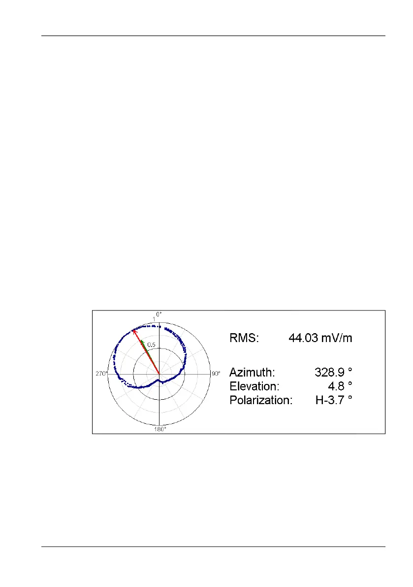
A Horizontal Scan results in a polar diagram that displays the measured
signal strength over a 360° angle. In the ideal situation, i.e. a transmitter of
constant output power level without any reflections, the polar diagram would
show the directional characteristics of the antenna. In such cases, the
bearing can be determined very easily from the signal maximum.
Figure 62: Ideal Horizontal Scan situation: The polar diagram shows the directional
characteristic of the antenna. Interpretation is easy; the bearing of the
signal source can be determined without problems.
In reality, a large number of reflections are superimposed on the actual
signal, making the polar diagram difficult to interpret. Such reflections occur
due to natural changes in ground level, large metal objects such as vehicles,
and street canyons. In most cases, though, automatic evaluation of the
polar diagram to determine the bearing will lead to the correct result.