V10/V7.5/V5/V3.5 Installation and Operation Manual Page 2-9
Section 2 Preparation for Use and Installation Issue 3.5
2.2.12 External Interlocks
The external electrical interlock circuit is
connected between XMTR INTLK
terminals TB1-1 and TB1-2 of the remote
interface PWB (A44). It must present a
short circuit (low impedance) between the
terminals when the interlock circuit is
intact and it is safe to enable the RF
output. It must present an open circuit
when any interlock switch is activated and
the RF output requires inhibition. Any
number of serial interlock switches may
be installed.
2.2.13 Remote Control Circuits
The transmitter control/monitoring
functions can be facilitated by means of a
conventional remote control interface or
serial port (using the NxLink module), all
available via connection to the remote
interface PWB (A44). See paragraph
2.2.14 for a description of the serial port
features. Remote control inputs are polled
(sampled) every 100 ms. Ensure the
active pulse duration is a minimum of 100
ms. The on/off status, active (A/B) exciter/
IPA/IPA PS/Fan PS, active power preset
(1-6), RF power level, and system reset
can be controlled remotely by switching
circuits.
NOTE
Unless noted, all remote interfacing is
done via the remote interface PWB (A44).
External control circuits are interfaced to
the transmitter through opto-couplers on
the remote interface PWB. The opto-
couplers buffer/isolate the external circuits
and prevent unwanted transients from
affecting transmitter operation. These
opto-couplers only have influence when
Remote control is selected. All external
input/output interface connections are
shown in Figure 2-7a (V10/V7.5) or 2-7b
(V5/V3.5). The remote interface PWB
contains circuits that allow the user to
select an internal (single ended input) or
external (differential input) dc power
supply as the current source for the opto-
coupler associated with each controlled
function.
The switching circuit for each remotely
controlled function must be the equivalent
of a normally open/held closed, spring-
loaded (momentary) switch. Each must be
configured to operate as a single ended
input using the transmitter's regulated
15 V as the dc volts source (see Figure
2-4), or as a differential input using an
external dc power supply (5 V to 30 V) as
the dc volts source (see Figure 2-5). Each
control function has positive and negative
input terminals on the remote interface
PWB to accommodate the selected
configuration.
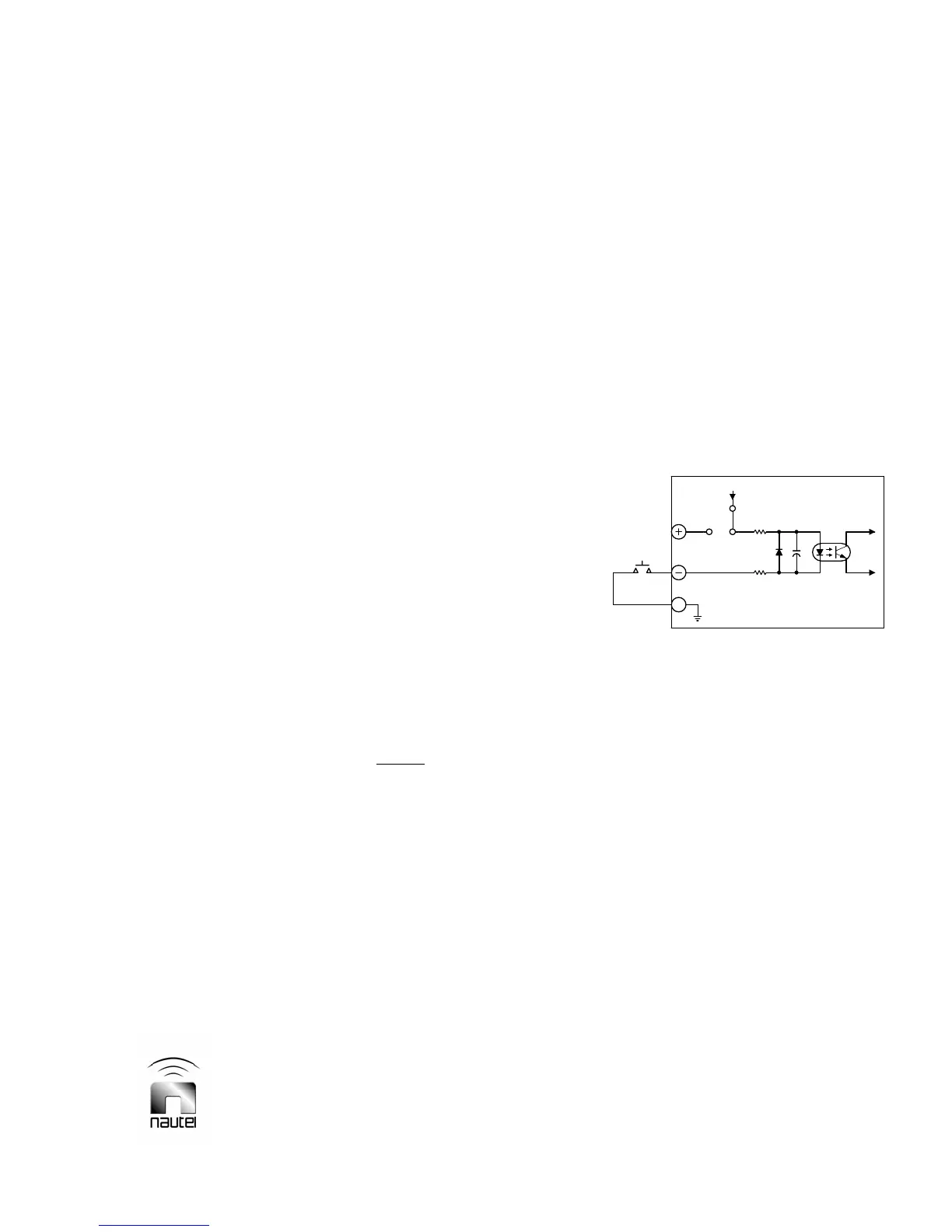
Figure 2-4 Single Ended Input Selected
Single Ended Input (Internal V dc)
When the transmitter's regulated +15 V is
used as the current source for a control
function's opto-coupler, its circuit on the
remote interface PWB must be configured
for a single ended input. The 3-pin header
associated with the control function must
have its 2-socket shunt post connected as
depicted in Figure 2-4, noting pins 2 and 3
of the header are shorted by the shunt
post. A negative logic command (active
state is a current-sink-to-ground) must be
applied to the control's negative (-) input
pin. The active command should be of
sufficient duration (minimum 100 ms) to
ensure being sampled. See Table 2-3 or
Figure 2-7a (V10/V7.5) or 2-7b (V5/V3.5)
for dc return (ground) locations.
3
PWB
1 2
+15V
E#
S1830085 V3
INTERFACE
REMOTE
REMOTE SELECTION CIRCUITRY
CONFIGURED FOR INTERNAL
DC VOLTS