Page 2-12 V10/V7.5/V5/V3.5 Installation and Operation Manual
Issue 3.5 Section 2 Preparation for Use and Installation
2.2.15.1 RF Monitor Samples
A true sample of the RF output voltage is
provided on the RF power probe
assembly’s (A42) RF MONITOR BNC
connector (J3) at the output of the
transmitter. This output should be applied
to a modulation monitor with 50 Ω input
impedance. It may also be monitored by
an oscilloscope during maintenance
procedures. Nominal levels (for rated
power) are as follows:
Transmitter, Mode, Power RF Monitor
V10, FM, 10,000 W 2.5 V
V10, FM+HD, 7,300 W 2.2 V
V10, HD, 2,800 W 2.2 V
V7.5, FM, 7,500 W 2.2 V
V7.5, FM+HD, 5,480 W 1.9 V
V7.5, HD, 2,100 W 1.9 V
V5, FM, 5,000 W 1.7 V
V5, FM+HD, 3,650 W 1.6 V
V5, HD, 1,400 W 1.6 V
V3.5, FM, 3,750 W 1.5 V
V3.5, FM+HD, 2,740 W 1.4 V
V3.5, HD, 1,050 W 1.4 V
True samples of the IPA amplifier(s)
output voltage are provided on the IPA
splitter’s (A21 and A22, if applicable) IPA
RF MONITOR BNC connector (J3) at the
rear of the transmitter. These outputs
should be applied to a modulation monitor
with 50 Ω input impedance. Nominal
levels (based on required IPA power) are
as follows:
Transmitter, Mode, Power
IPA
Monitor
V10, FM, 10,000 W (250 W IPA) 1.0 V
V10, FM+HD, 7,300 W 0.4 V
V10, HD, 2,800 W 0.4 V
V7.5, FM, 7,500 W (250 W IPA) 1.0 V
V7.5, FM+HD, 5,480 W 0.4 V
V7.5, HD, 2,100 W 0.4 V
V5, FM, 5,000 W (250 W IPA) 1.0 V
V5, FM+HD, 3,650 W 0.2 V
V5, HD, 1,400 W 0.3 V
V3.5, FM, 3,750 W (250 W IPA) 1.0 V
V3.5, FM+HD, 2,740 W 0.2 V
V3.5, HD, 1,050 W 0.3 V
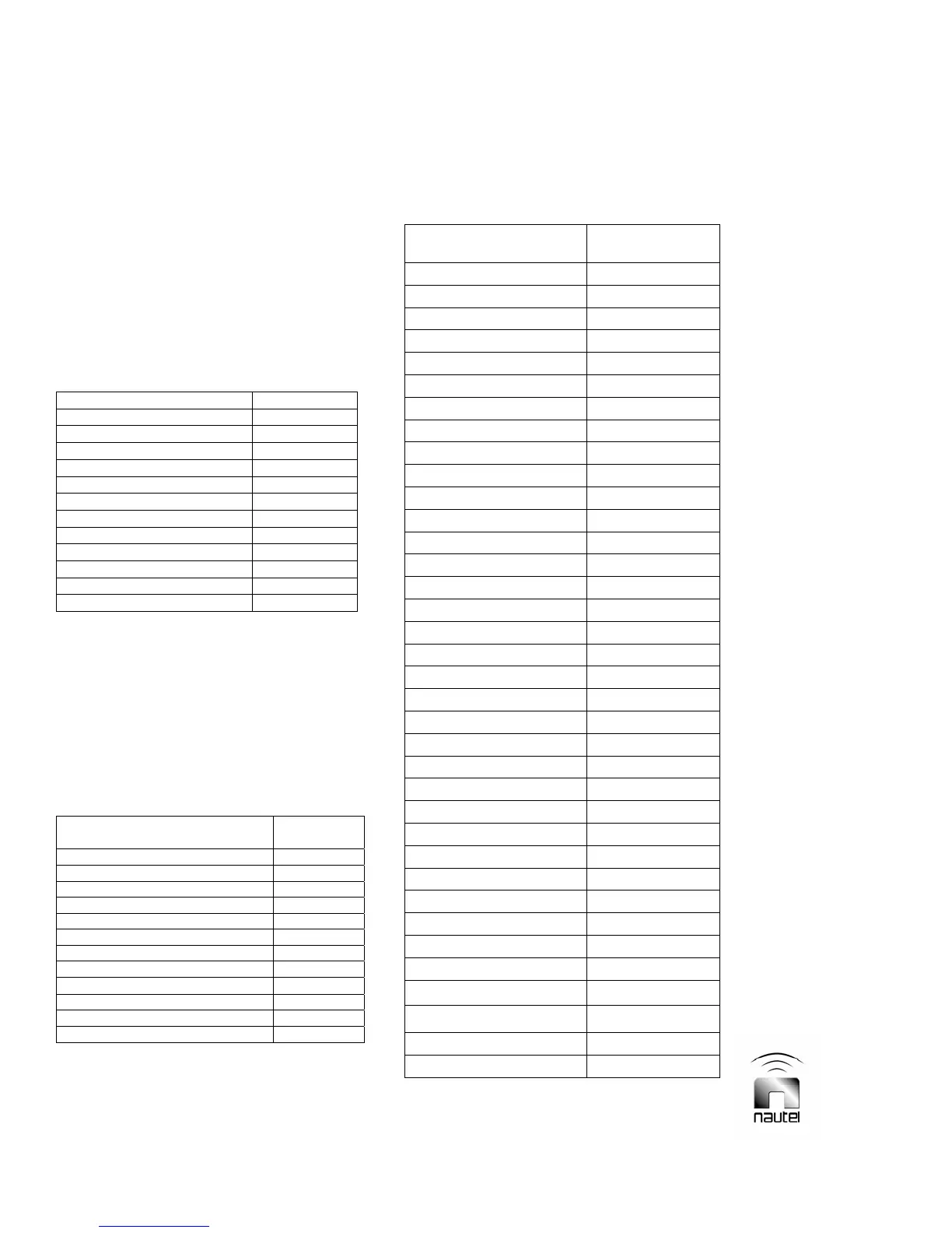
Table 2-4: Remote Monitor Connections
(TB1, J4 or J6 of remote interface PWB)
Remote Alarm, Status
or Sample
Terminal or Pin
Summary Alarm TB1-4
Interlock Open Alarm TB1-5
Low Battery/Memory Fail TB1-6
Low RF Alarm TB1-7
Changeover Alarm TB1-8
PA Fail Alarm TB1-9
High Reflected Power Alarm TB1-10
High Temperature Alarm TB1-11
Transmitter Ready TB1-13
RF On Status TB1-14
Exciter Status TB1-15
IPA Status TB1-16
+15 V dc supply TB1-18
Forward Power Sample TB1-20
Reflected Power Sample TB1-21
Ground TB1-3,12,17,19
Preset 1 Status J4-15
Preset 2 Status J4-16
Preset 3 Status J4-17
Preset 4 Status J4-18
Preset 5 Status J4-19
Preset 6 Status J4-20
Remote Status J4-22
IPA Power Supply Status J4-23
Fan Supply Status J4-24
Valid Data Status J4-26
Ground J4-1,14,21,33,34,35
Ac Fault Alarm J6-1
Power Supply Fail Alarm J6-2
IPA/RF Fail Alarm J6-3
PA Voltage Sample J6-9
Exciter Forward Pwr Sample J6-10
Intake Air Temp Sample J6-11
Exhaust Air Temp Sample J6-12
Total PA Current Sample J6-21
Ground J6-7,8,13,14,20,33