V10/V7.5/V5/V3.5 Installation and Operation Manual Page 3-23
Section 3 Operating Instructions Issue 3.5
NOTE
Pressing the Power - Increase or Decrease
button at any time, regardless of the GUI
screen, will automatically enter the Edit
Preset screen for the active preset and will
highlight the Power parameter. If Power -
Increase or Decrease is pressed again, the
Power parameter will change accordingly.
Press Save to activate the change.
(b) To edit a preset parameter, highlight the
desired parameter (using f and g) and
press Edit.
- Edit the power level, if desired, using the
Power - Increase and Decrease buttons
or f and g [for FM mode, each
increment is 100 W (V10/V7.5) or 50 W
(V5/V3.5); for FM+HD and HD modes,
each increment is 10 W]; holding the
button increases the rate of change].
- Edit the operating frequency, if desired,
using the f and g buttons (in 100 kHz
steps; holding the button increases the
rate of change).
NOTE
If the transmitter’s frequency is changed,
ensure the frequency of any associated
equipment (M50, etc.) is also changed.
- Edit the mode of operation [FM (analog),
HD (all digital), or FM+HD (hybrid)]. If the
operating mode is FM, you can also edit
the following parameters:
• PA ALC [Y (default) or N]
• IPA Power (in watts; 250 W default)
• IPA ALC [Y (default) or N]
- The above parameters have been factory
set and should not require adjustment.
- If you press Edit for any parameter,
press Save to activate changes or Back
to cancel the edit.
- Press Back to return to power control
screen.
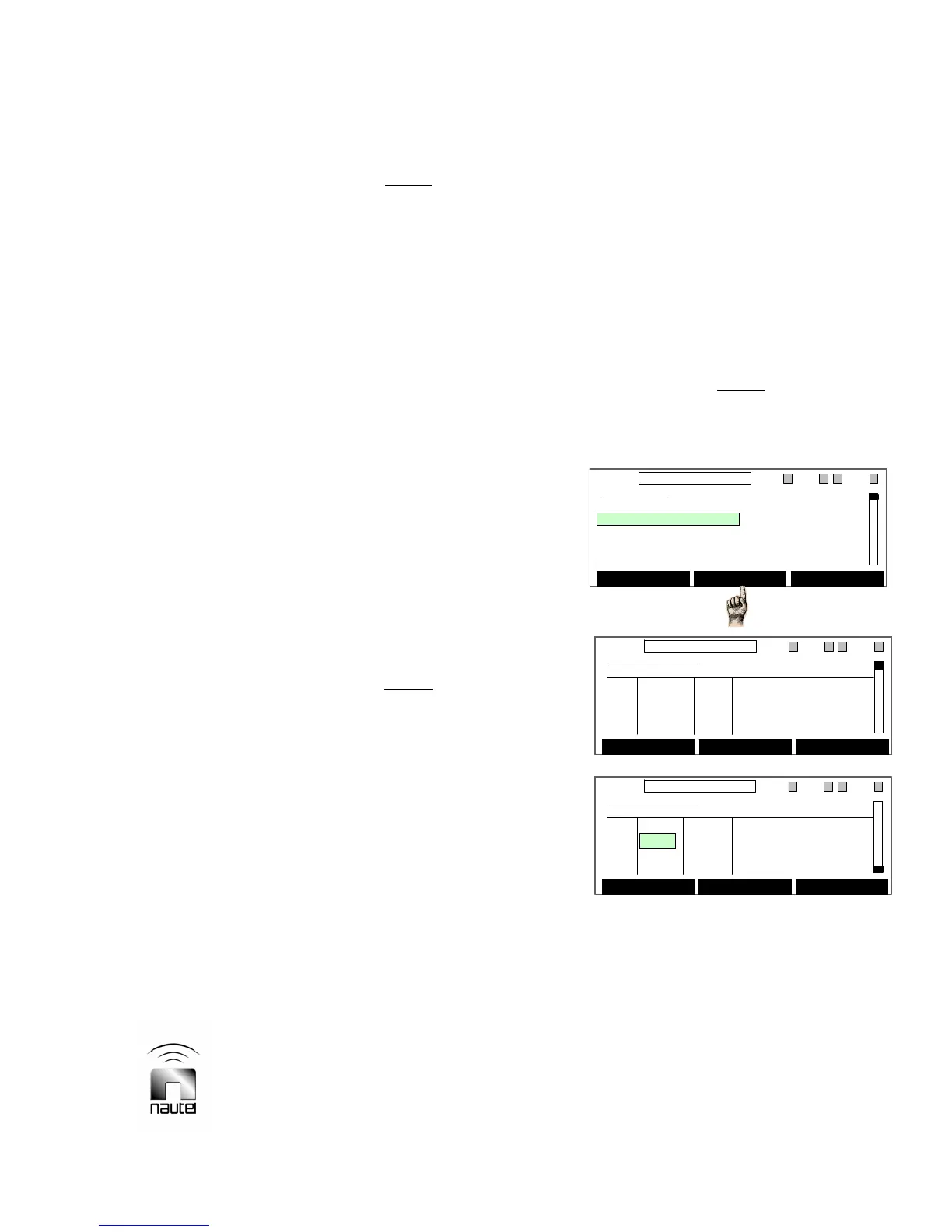
3.6.5 View RF Module Status and
Fan Speed
Critical diagnostic information for the RF
power modules (A - H and IPA modules A
and B for V10 transmitters; A – C, E – G, and
IPA modules A and B for V7.5 transmitters;
A - D and the IPA module for V5 transmitters;
A - C and the IPA module for V3.5
transmitters) and cooling fan speed can be
monitored as follows:
NOTE
The Module Status menu is displayed for
monitoring purposes only. Module status
cannot be altered from this menu.
(a) From the main menu, highlight Module
Status (using f and g) and press
Select. A Module Status screen will
appear that shows the current and bias
voltage for each PA in the module being
viewed as well as the PA voltage,
temperature, intermediate RF level and
fan speed.
Main Menu
Power Control
Module Status
Events Log
Software Version
Meters Presets
Select Back
11:26 98.10MHz 0.00kW 1 EXA IPAA/A FanA
Main Menu
Power Control
Module Status
Events Log
Software Version
Meters Presets
Select Back
11:26 98.10MHz 0.00kW 1 EXA IPAA/A FanA
Module Status
Curr. Bias PA Module A
Q1 0 A 0 V PA Volts 0 V
Q2 0 A 0 V Temperature 31 C
Q3 0 A 0 V Intm RF Lvl 0 V
Q4 0 A 0 V Fan Speed 0 RPM
Reset Back
11:26 98.10MHz 0.00kW 1 ExA IPAA/A FanA
Module Status
Curr. Bias PA Module A
Q1 0 A 0 V PA Volts 0 V
Q2 0 A 0 V Temperature 31 C
Q3 0 A 0 V Intm RF Lvl 0 V
Q4 0 A 0 V Fan Speed 0 RPM
Reset Back
11:26 98.10MHz 0.00kW 1 ExA IPAA/A FanA
Module Status
Curr. Bias PA Module A
Q1 0 A 0 V PA Volts 0 V
Q2 0 A 0 V Temperature 31 C
Q3 0 A 0 V Intm RF Lvl 0 V
Q4 0 A 0 V Fan Speed 0 RPM
Reset Back
11:26 98.10MHz 0.00kW 1 ExA IPAA/A FanA
Module Status
Curr. Bias IPA Module
Q4 A 0 A 3.25 V PA Volts 0 V
Q3 B DSBL 3.35 V Temperature 32 C
RF Lvl 0 V
Reset Back
11:26 98.10MHz 0.00kW 1 ExA IPAA/A FanA
Module Status
Curr. Bias IPA Module
Q4 A 0 A 3.25 V PA Volts 0 V
Q3 B DSBL 3.35 V Temperature 32 C
RF Lvl 0 V
Reset Back
11:26 98.10MHz 0.00kW 1 ExA IPAA/A FanA