V10/V7.5/V5/V3.5 Installation and Operation Manual Page 3-3
Section 3 Operating Instructions Issue 3.5
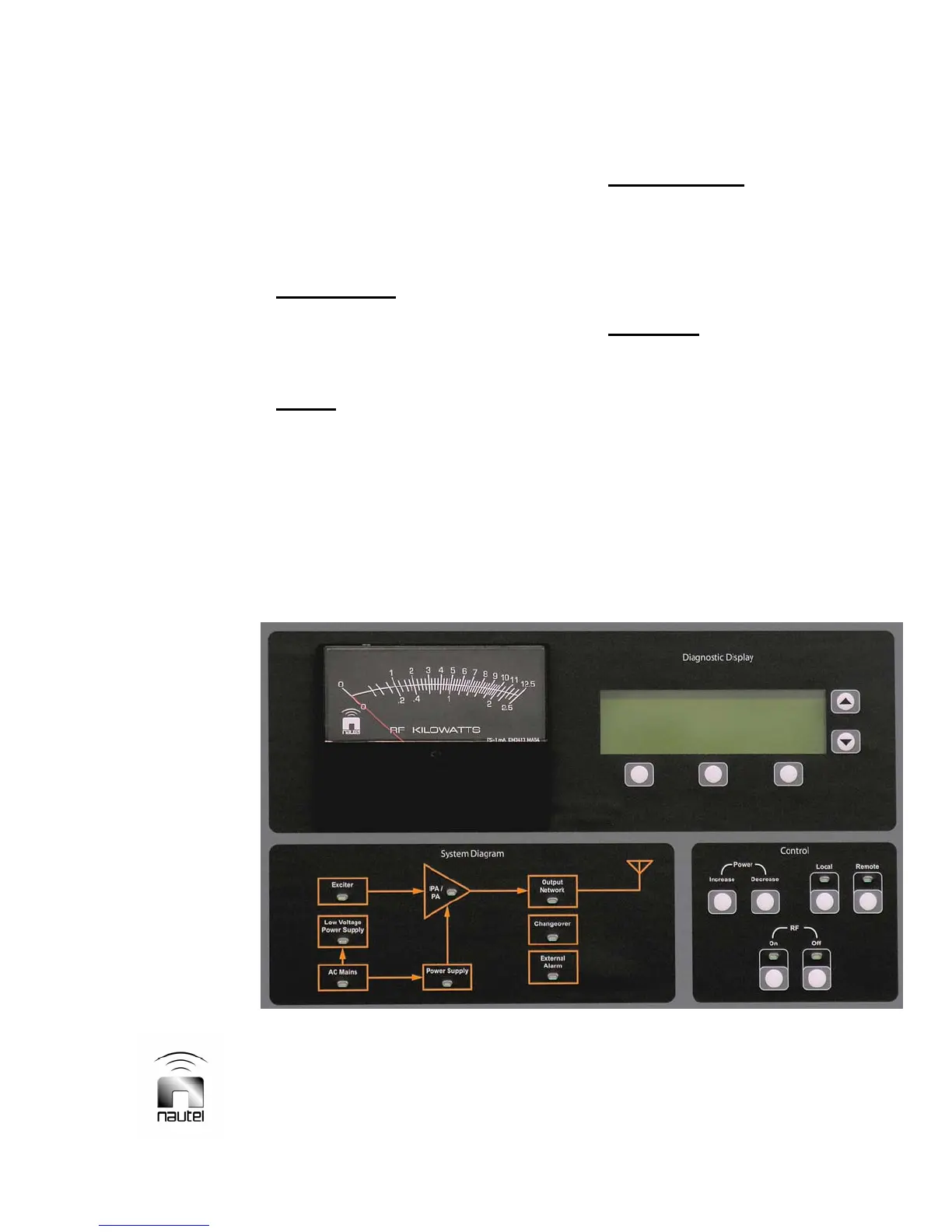
3.5.1 Front Panel
The front panel is the primary local user
interface for the transmitter. Control and
indicators are grouped into four sections of
the panel (see Figure 3-1) as follows:
• System Diagram
- a simple block
diagram of the transmitter complete with
alarm lamps. Refer to Figure 3-2 and
Table 3-1 for a description of the controls
and indicators.
• Control
– push-button switches that
allow convenient control of the
transmitter’s RF status (on or off and
increase or decrease) and its operator
control source (local or remote). The RF
Off switch is functional regardless of local
or remote selection. Refer to Figure 3-3
and Table 3-2 for a description of the
controls and indicators.
• Diagnostic Display
– a menu-driven user
interface screen - with five associated
push-buttons - which allows control and
monitoring of the transmitter’s critical
parameters and modes of operation. See
paragraph 3.6 for a full description of the
diagnostic display.
• Power Meter
– the RF KILOWATTS
meter displays forward power on the
upper scale and reflected power on the
lower scale. Scale selection and meter
enabling is selected using the diagnostic
display (see paragraph 3.6.10).
Figure 3-1: Transmitter Front Panel (Primary User Interface)
 Loading...


