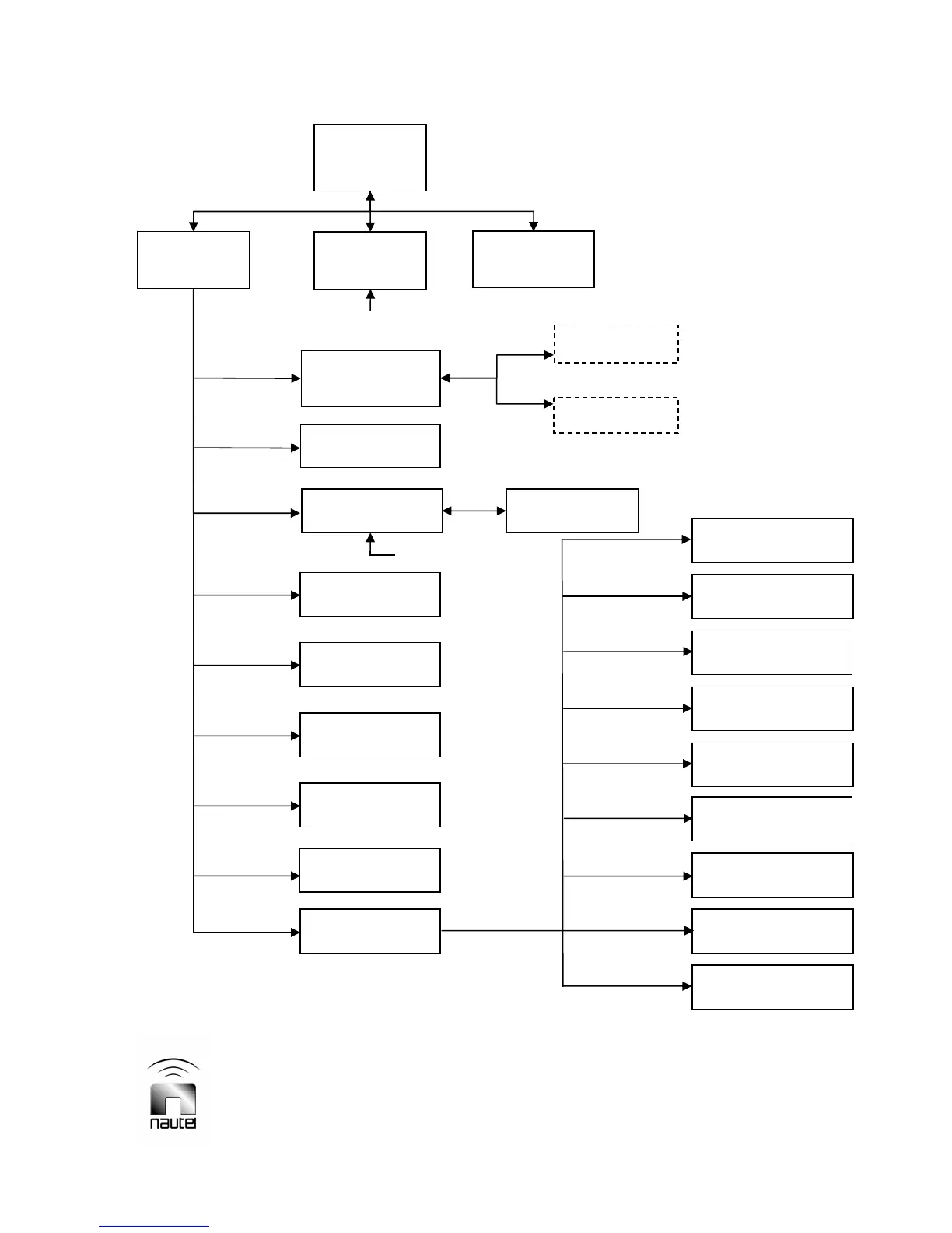
FOR QUICK REFERENCE TO A GUI FUNCTION: Locate the desired function in the flow diagram below, then
refer to the referenced paragraph (e.g. 3.6.2) for further information.
V10/V7.5/V5/V3.5 Installation and Operation Manual Page 3-21
Section 3 Operating Instructions Issue 3.5
Figure 3-11 – Flow Diagram – Diagnostic Display Menu Functions
** - Hardware settings are established at
Nautel during factory testing. User
adjustments - which are not normally
required - should only be performed by
trained personnel.
Ext Analog
Samples (3.6.11)
Calibrate HD PA/IPA
Volts (3.6.12.1)
Calibrate External
Meter (3.6.12.2)
Calibrate Meters
(3.6.12.3)
Setup Mode
(3.6.12.4)
Setup PA Bias
(3.6.12.5)
Setup Thresholds
(3.6.12.6)
System Configuration
(3.6.12.7)
Save/Recall Factory
Settings (3.6.12.8)
Main
Screen
(3.6.2)
Main Menu
(3.6.2)
Changeover
(3.6.13)
Status
(3.6.3)
Change Power,
Freq or Mode
(3.6.4)
Edit Preset 1
Edit Preset 6
Events Log
(3.6.6)
View Event
(3.6.6)
Clear Log
Module Status
(3.6.5)
Software Version
(3.6.7)
Meter Presets
(3.6.8)
Reset
Real Time Clock
(3.6.9)
Ext Meter &
Contrast (3.6.10)
Hardware Settings
(3.6.12) **
throu
h
NxLink Configuration
(3.6.12.9)
** - Optional. Displayed only when
NxLink is installed and
communicating with transmitter.