Page 2-10 V10/V7.5/V5/V3.5 Installation and Operation Manual
Issue 3.5 Section 2 Preparation for Use and Installation
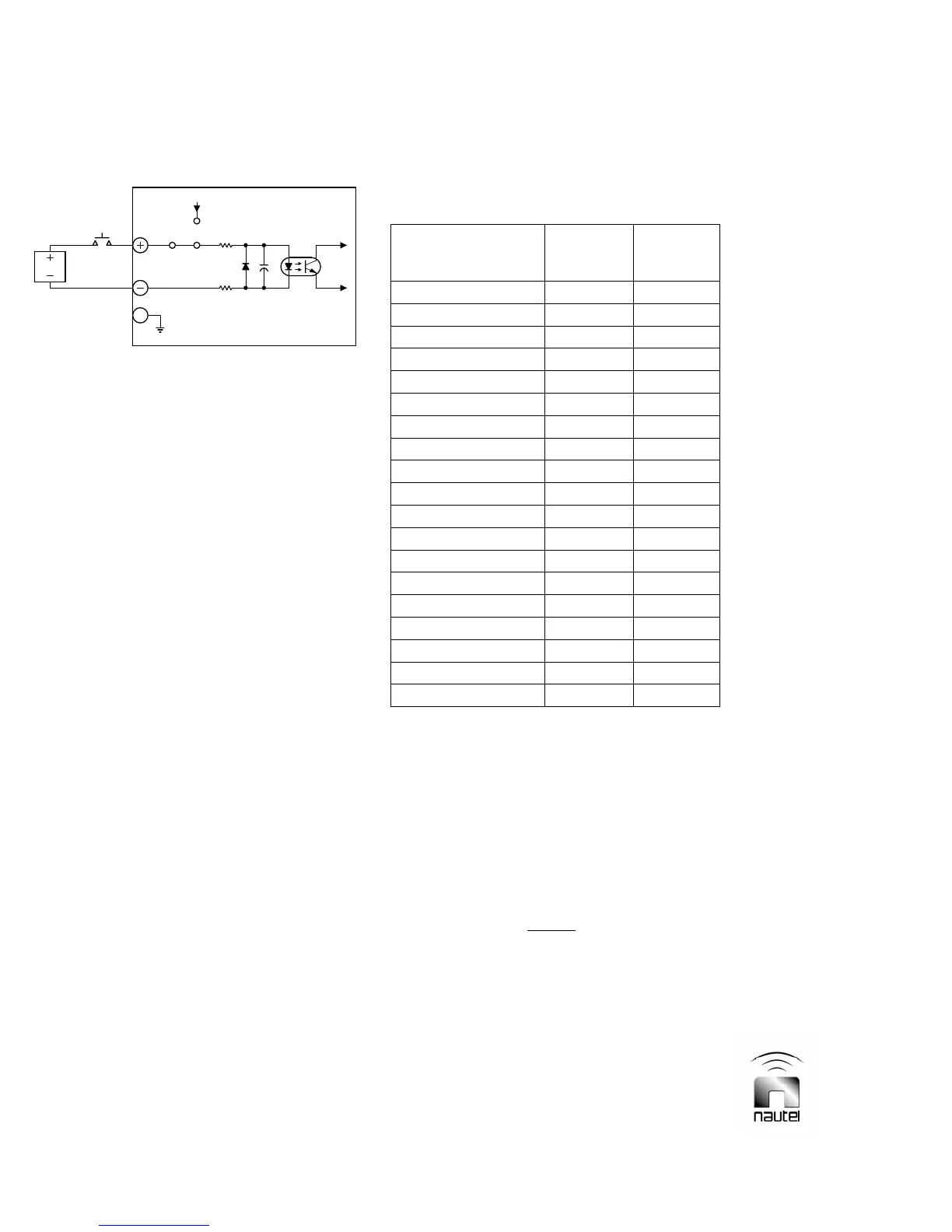
Figure 2-5 Differential Input Selected
Differential Input (External V dc)
When an external dc voltage (5 - 30 V) is
used as the current source for a control
function’s opto-coupler, the control
function's external switching circuit and
the remote interface PWBs selection
circuitry must be configured for differential
input. The 3-pin header associated with
the control function must have its 2-socket
shunt post connected as depicted in
Figure 2-5, noting pins 1 and 2 of the
header are shorted by the shunt post. The
normally open/held closed switch may be
located between the dc voltage's negative
output and the negative (-) input pin
(negative logic) or between its positive
output and the positive (+) input pin
(positive logic). The active command
should be of sufficient duration (minimum
100 ms) to ensure being sampled.
2.2.13.1 On/Off Control
The remote on/off circuitry controls the
on/off status of the RF power stage. It
comprises an on circuit (TB4-2/3) and an
off circuit (TB4-4/5).
2.2.13.2 Main Exciter Selection
The main exciter selection circuit selects
which exciter is enabled as the main
exciter. It comprises an A (TB3-2/3) and a
B (TB3-4/5) circuit.
2.2.13.3 Main IPA Selection
The main IPA selection circuit selects
which IPA (module for V10, PA for V5) is
enabled as the main IPA. It comprises an
A (TB3-7/8) and a B (TB3-9/10) circuit.
Table 2-3: Remote Control Connections
(TB3, TB4, J4 or J6 of remote interface PWB)
Remote
Control
SGL/DIFF
Jumper
Terminal/
Pin
+ / -
Exciter 'A' Select E2 TB3-2/3
Exciter 'B' Select E1 TB3-4/5
IPA 'A' Select E9 TB3-7/8
IPA 'B' Select E8 TB3-9/10
Reset E20 TB3-11/12
RF On E11 TB4-2/3
RF Off E10 TB4-4/5
Power Increase E16 TB4-7/8
Power Decrease E17 TB4-9/10
Preset 1 Select
E3 J4-2/3
Preset 2 Select
E4 J4-4/5
Preset 3 Select E15 J4-6/7
Preset 4 Select E14 J4-8/9
Preset 5 Select E13 J4-10/11
Preset 6 Select E12 J4-12/13
Fan Supply ‘A’ Select E7 J4-29/30
Fan Supply ‘B’ Select E6 J4-31/32
**IPA PS ‘A’ Select E21 J6-27/28
**IPA PS ‘B’ Select E18 J6-29/30
** Used in V5/V3.5 transmitters only
For V10/V7.5 transmitters, this circuit
simultaneously selects the main IPA
module and its associated IPA power
supply. For V5/V3.5 transmitters, a
separate remote control is available to
select the main IPA power supply (see
2.2.13.4).
NOTE
For V10/V7.5 transmitters, the remote
selection of the active IPA module is
ganged together with the remote selection
of the active IPA power supply.
For V5/V3.5 transmitters, the remote
selection of the active IPA PA is
independent from the remote selection of
the active IPA power supply.
3
PWB
1 2
+15V
EXTERNAL DC
PWR SUPPLY
E#
(+5V TO +30V)
S1830086 V4
INTERFACE
REMOTE
REMOTE SELECTION CIRCUITRY
CONFIGURED FOR EXTERNAL
DC VOLTS
27