V10/V7.5/V5/V3.5 Installation and Operation Manual Page 3-27
Section 3 Operating Instructions Issue 3.5
(b) The Ext Analog Samples screen shows
the parameter (e.g., Fwd Power and its
current level), the external sample
voltage (Sample Out1) for the
parameter’s current level and the Scaling
factor. Use f and g to select the
parameter to edit and press Select.
Table 3-8 External Analog Sample Outputs
Sample Parameter
Remote
Output
*Sample Out1 Fwd Power TB1-20
*Sample Out2 Refld Power TB1-21
*Sample Out3 PA VDC J6-9
*Sample Out4 IPA I/P Pwr J6-10
*Sample Out5 Intake Temp J6-11
*Sample Out6 Exhaust Temp J6-12
*Sample Out7
Tot. PA Curr J6-21
Sample Out8
User defined J6-22
Sample Out9
User defined J6-23
Sample Out10
User defined J6-24
Sample Out11
User defined J6-25
Sample Out12
User defined J6-26
* Sample Out1 - 7 are not user-configurable.
Remote output terminals or pins are located on
remote interface PWB A44
(c) Use f and g to highlight either the
parameter or the scaling factor. Press
Edit.
• If the parameter is selected for Edit, the
user can scroll (using f and g) through
the various metered parameters (see
default list in 3.6.8) that can be applied to
that particular Sample Out8 through 12
pin (see Table 3-8).
• If the Scaling factor is selected for Edit,
the user can adjust (using f and g) the
scaling factor, hence the Sample Out
voltage of the displayed parameter.
(d) When changes are complete, press Save
to store setting(s).
(e) Press Back to return to previous menu.
3.6.12 Change Hardware Settings
Certain hardware settings and parameters,
calibrated during factory testing, can be
changed for troubleshooting or in the event
that an out-of-tolerance condition occurs.
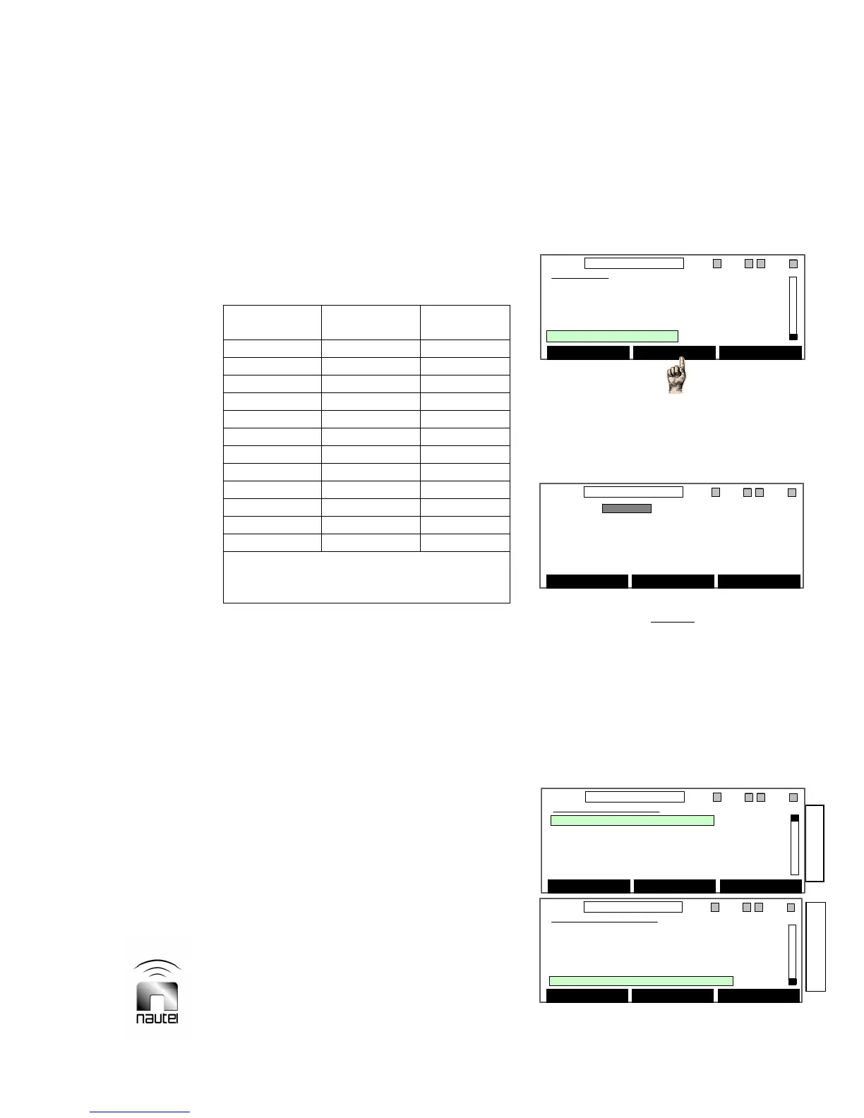
(a) From the main menu, highlight Hardware
Settings (using f and g) and press
Select.
NOTE
Hardware settings are established at Nautel
during factory testing and recorded in the
Critical Parameters sheet. User adjustments
- which are not normally required - should
only be performed by trained personnel.
After pressing Continue, the following
screen (note the scroll bar position) will
be displayed:
Main Menu
Meter Presets
Real Time Clock
Ext Meter & Contrast
Ext Analog Samples
Hardware Settings
Select Back
11:26 98.10MHz 0.00kW 1 ExA IPAA/A FanA
Main Menu
Meter Presets
Real Time Clock
Ext Meter & Contrast
Ext Analog Samples
Hardware Settings
Select Back
11:26 98.10MHz 0.00kW 1 ExA IPAA/A FanA
WARNING
Changing the settings on the
following screens should only
be done by trained Personnel.
Continue Back
11:26 98.10MHz 0.00kW 1 ExA IPAA/A FanA
WARNING
Changing the settings on the
following screens should only
be done by trained Personnel.
Continue Back
11:26 98.10MHz 0.00kW 1 ExA IPAA/A FanA
Top of Screen
Bottom of Screen
Hardware Settings
Calibrate HD PA/IPA Volts
Calibrate External Meter
Calibrate Meters
Setup Mode
Setup PA Bias
Select Back
11:26 98.10MHz 0.00kW 1 ExA IPAA/A FanA
Hardware Settings
Calibrate HD PA/IPA Volts
Calibrate External Meter
Calibrate Meters
Setup Mode
Setup PA Bias
Select Back
11:26 98.10MHz 0.00kW 1 ExA IPAA/A FanA
Hardware Settings
Setup PA Bias
Setup Thresholds
System Configuration
Save/Recall Factory Settings
NxLink Configuration
Select Back
11:26 98.10MHz 0.00kW 1 ExA IPAA/A FanA
Hardware Settings
Setup PA Bias
Setup Thresholds
System Configuration
Save/Recall Factory Settings
NxLink Configuration
Select Back
11:26 98.10MHz 0.00kW 1 ExA IPAA/A FanA