WHAT TO DO IF... (troubleshooting guide)
2 Using the transmitter, perform door opening and closing tests and ensure
thatthemovementcorrespondstospecications.
Test several times to assess smooth operation of the door and check for any
defects in assembly or adjustment and any possible points of friction.
3 Checkoperationofallsystemsafetydevicesoneatatime(photocells,sensi-
tive edges, etc.). Photocells: Activate the device during a Closing manoeuvre
and check that the control unit stops the manoeuvre and activates a total
inversionofthemovement(thecourtesylightemits2ashes,twice).Sensi-
tive edges: Activate the device during an Opening or Closing manoeuvre and
check that the control unit stops the manoeuvre and activates a short inver-
sionofthemovement(thecourtesylightemits4ashes,twice).
4 To check the photocells, and to ensure there is no interference with other
devices,passacylinder(diameter5cm,length30cm)throughtheoptic
axisjoiningthepairofphotocells(g. 45):passthecylinderrstclosetothe
TX photocell, then close to the RX and lastly at the centre between the two.
Ensure that in all cases the device engages, changing from the active status
to alarm status and vice versa, and that the envisaged action is generated in
thecontrolunit(forexamplemovementinversionintheClosing manoeuvre).
5 MeasuretheforceasspeciedinthestandardEN12445.Ifthemotorforce
control is used as an auxiliary function for reduction of impact force, test and
identify the setting that obtains the best results.
6 Activate a closing manoeuvre and check impact force of the door against
thetheoorsurface.Ifnecessary,testbydischargingpressuretoobtainthe
best results.
AUTOMATION COMMISSIONING
Commissioning can only be performed after positive results of all test
phases. Partial or “makeshift” commissioning is strictly prohibited.
1 Prepare the automation technical documentation, which must contain the
followingdocuments:Overalllayoutdrawing(seeexampleing. 6, 7, 8),
electricalwiringdiagram(seeexampleinSTEP6), risk assessment and rel-
ativesolutionsadopted(seeformstobecompiledonthewebsitewww.
niceforyou.com), manufacturer’s declaration of conformity for all devices
CAUTION! – All operations in this section must be performed exclusive-
ly by skilled and qualied personnel, in observance of the instructions
in the manual, and current local legislation and safety standards in the
place of installation.
CONNECTING THE AUTOMATION TO THE ELECTRICAL MAINS
CAUTION!– When making this connection, the electrical mains power line
mustbeequippedwithshort-circuitprotectiondevice(betweentheautomation
and the mains).
The electrical mains line must also be equipped with a power disconnect device
(withovervoltagecategoryIII,i.e.minimumgapbetweencontactsof3mm)or
an equivalent system such as socket with removable plug.
This device, when necessary, guarantees fast and safe disconnection of the
power supply and therefore must be placed in a location visible from the auto-
mation. If the power disconnect device is not in the vicinity of the automation
andnotvisiblefromthelatter,itmustbettedwithalockoutfacilitytoprevent
inadvertent or unauthorised connection.
Note – The disconnect devices are not supplied with the product.
AUTOMATION TESTING AND COMMISSIONING
These are the most important phases of automation set-up to ensure maxi-
mum system safety. The testing procedure described can also be performed
as a periodic check of automation devices.
Testing and commissioning of the automation must be performed by skilled
andqualiedpersonnel,whoareresponsibleforthetestsrequiredtoverify
the solutions adopted according to the risks present, and for ensuring obser-
vance of all legal provisions, standards and regulations, and in particular all
requirements of the standard EN 12445, which establishes the test methods
for checking automations for garage doors.
AUTOMATION TESTING
1 EnsurethatallspecicationsinSTEP1regardingsafetyhavebeenstrictly
observed.
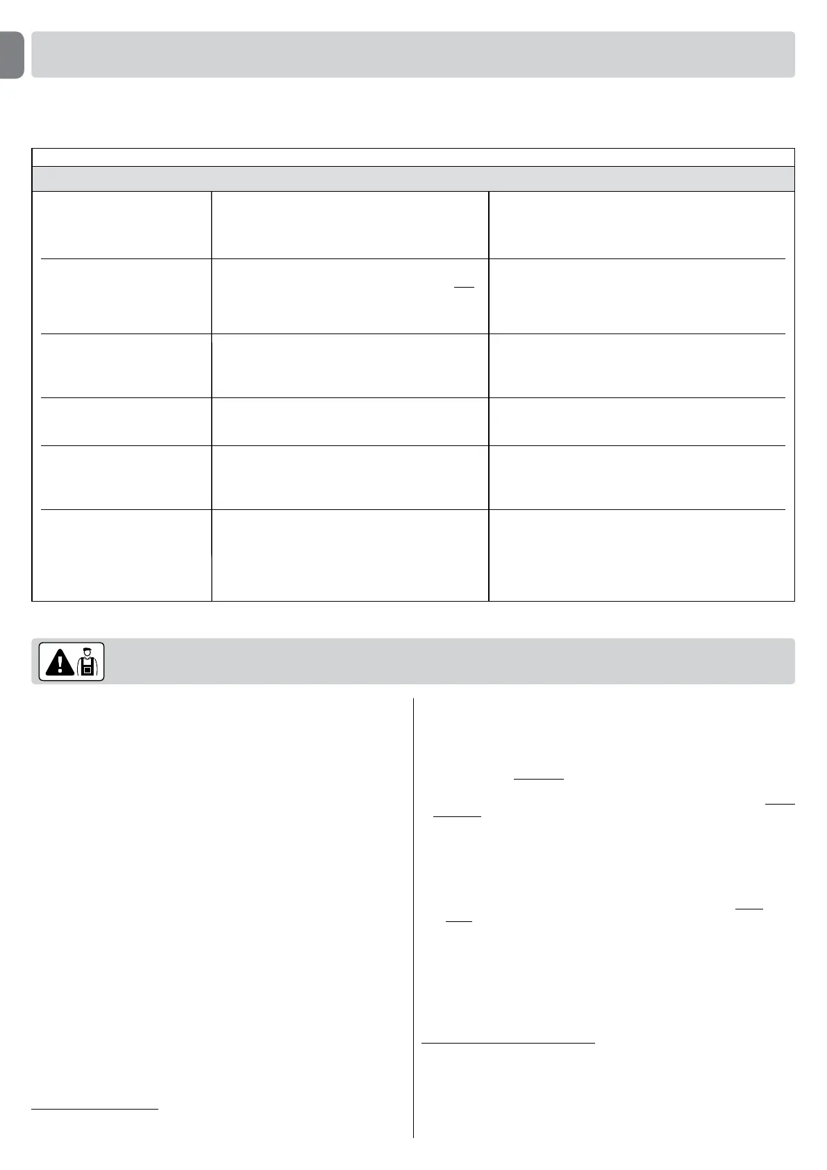
Tasks reserved for qualied technicians
Flashes
2ashes-pause-2ashes
3ashes-pause-3ashes
4ashes-pause-4ashes
5ashes-pause-5ashes
6ashes-pause-6ashes
7ashes-pause-7ashes
Problem
During the Closing manoeuvre, the door stops and
inverts the current movement.
During the Opening or Closing manoeuvre the door
blocks suddenly and the control unit activates a brief
inversion of the manoeuvre in progress
During the Opening or Closing manoeuvre the door
blocks suddenly and the control unit activates a Stop
followed by a brief inversion of movement.
The automation does not respond to commands.
After a series of manoeuvres sent consecutively, the
automation is blocked.
The automation does not respond to commands.
Solution
Thisreactioniscausedbytheactivationofaspecicpair
of photocells in the system, on detection of an obstacle.
Therefore remove the obstacle on the trajectory of these
photocells.
The leafs are subject to increased friction due to a sudden
obstruction(gustofwind,vehicle,personetc.).Ifadjust-
ment to sensitivity is required, refer to the Chapter “Adjust-
ments and other optional Functions”.
Asafetydeviceinstalled(otherthanphotocells,suchassensi-
tive edges) has detected a sudden obstacle.
Therefore remove the obstacle.
Thereisasystemcongurationerror.Deletetheentiremem-
ory of the control unit and repeat installation.
The maximum admissible number of consecutive manoeu-
vres has been exceeded, causing excessive overheating. Wait
for a few minutes to enable the temperature to return below
the maximum limit.
Error in internal electric circuits. Disconnect all power circuits,
wait a few seconds and then re-connect. Retry a command; if
the automation does not respond this may indicate a serious
fault with the electrical board of the control unit or motor wir-
ing. Check and make replacements as necessary.
During normal operation, the control unit constantly monitors the automation processes and is designed to indicate any faults that arise, by means of a pre-set
sequenceofashesemittedbythecourtesylightandredled“L1”onthecontrolunit(thediagnosticsashesalwaysrefertothelastactionperformedbythe
automation).Foranexplanationofthenumberofashesandassociatedcause,refertoTable 6 below:
TABLE 6
8 – English
EN
 Loading...