WARNING!
Some components shown in g. 2 are optional and may not be
supplied in the pack.
List of components:
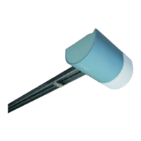
[a] - electromechanical gearmotor
[b] - integral guide
[c] - gearmotor ceiling mounting brackets
[d] - gearmotor wall-mounting brackets
[e] - mechanical stop for carriage travel limit
[f] - chain gear
[g] - drive chain
[h] -doordriverod(for sectional doors only)
[i] - drive carriage
[l] - automation release knob and cord
[m] - bracket for connection of drive rod to door
[n] - oscillating arm and relative drive rod
(mod.SPA5, for up-and-over doors only)
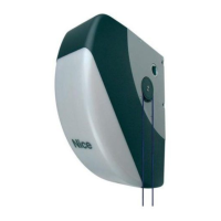
[o] -pairofphotocells(wall-mounted)mod.MOF/MOFO
[p] -transmitter(portable)mod.FLO4R-S
[q] - radio control keypad mod. MOTXR(wall-mounted)
[r] - Metalhardware(screws,washers,etc.)
*
(
*
) Note – The screws required for wall-xture of components are not
included in the pack, as their type depends on the material and thick-
ness of the door in which they are inserted.
STEP 3
PRELIMINARY INSTALLATION WORK
Before proceeding with installation, check the condition of the product compo-
nents, suitability of the selected model and conditions of the intended installa-
tion environment.
IMPORTANT – The gearmotor
cannot be used to power a door that
is not fully efcient and safe
. Neither can it solve defects caused
by poor installation or insufcient maintenance of the door itself.
3.1 – CHECKING SUITABILITY OF THE ENVIRONMENT AND
THE DOOR TO BE AUTOMATED
• In the case of automating a projecting up-and-over door, ensure that move-
ment does not obstruct public roads or pavements.
• Ensure that the mechanical structure of the door is suitable for automation
and complies with local standards.
• Check stability of the mechanical structure of the door, ensuring that there is
no risk of guides coming out of their seats.
• Move the door manually to open and close, checking that movement has the
same degree of friction throughout all points of travel (no increase in friction
must occur).
• Ensure that the door is correctly balanced: in other words, if left stationary
(manually)itmustnotmovefromanyposition.
• Ensure that the space around the automation enables safe and easy manual
release.
• Ensure that the selected surfaces for installation of the various devices are
solidandguaranteeastablexture.
• Ensure that all devices to be installed are in a sheltered location and pro-
tected against the risk of accidental impact.
•Ensurethattheselectedsurfacesforxingthephotocellsareatandenable
correct alignment between photocells.
3.2 – CHECKING PRODUCT APPLICATION LIMITS
Toascertainsuitabilityoftheproductwithrespecttothespecicfeaturesofthe
door and area to be automated, the following checks should be performed as
well as a check for compliance of the technical data in this paragraph and the
chapter “Product technical specications”.
• Ensure that the dimensions and weight of the door are within the following
limits of use.
Note – The shape of the door and weather conditions, such as the presence
of strong winds, can reduce the above maximum values. In these cases it is
important to measure the force required to move the door in the worst condi-
tions and compare these with the technical specications of the gearmotor.
SHEL60KIT SHEL75KIT
Sectional doors 350 x 240 cm 400 x 240 cm
Projecting 350 x 280 cm 400 x 280 cm
up-and-over doors
Non-projecting 350 x 220 cm 400 x 220 cm
up-and-over doors
• Ensure that the area for mounting the gearmotor and guide is compatible
with the overall dimensions of the automation to be installed. Then ensure that
the minimum and maximum clearances can be observed as shown in g. 3,
4 and 5.
Caution! – If the results of these checks do not conform to speci-
cations, this model cannot be used to automate your door.
STEP 4
4.1 – PRELIMINARY SET-UP WORK
4.1.1 – Typical reference system
Fig. 6, 7, 8 provide an example of an automation system set up with the com-
ponents compatible with this product. These parts are positioned according to
a typical standard layout. The following components are used:
a - Electromechanical gearmotor
b - Carriage sliding guide
c - drive carriage
d - mechanical stop for carriage travel limit
e - carriage manual release knob
f - bracket for connection of carriage to door
g - pair of photocells (wall-mounted) mod. MOF/MOFO
h - radio control keypad (wall-mounted) mod. MOTXR
i - portable transmitter mod. FLO4R-S
l - Pushbutton
4.1.2 – Establishing positions of components
With reference to gs. 6, 7, 8,
locate the approximate position for installa-
tion of each component envisaged in the system.
4.1.3 – Establishing the device connection layout
With reference to g. 10 and STEP 6 establish the connection layout for all
system devices.
4.1.4 – Checking the tools required for the work
Before starting installation, ensure that there is all equipment and materials
requiredfortheworkconcerned(seeexampleing. 9); also ensure that all
items are in good condition and comply with local safety standards.
4.1.5 – Preliminary set-up work
Dig the routes for the ducting used for electrical cables, or alternatively external
ducting can be laid, after which the pipelines can be embedded in concrete
andotherpreparationworkfortheinstallationcanbecompletedtonalisethe
site ready for subsequent installation operations.
CAUTION! – Position the ends of the ducting used for electrical cables
in the vicinity of the points envisaged for xture of the various compo-
nents.
Notes:
• The ducting serves to protect electrical cables and prevent accidental dam-
age in the event of impact.
• The “xed” control devices must be visible from the door but positioned far
from moving parts and at a minimum height of 150 mm.
4.2 – LAYING THE ELECTRIC CABLES
With the exception of the system connection to the mains by means of the
plugandsocket,therestofthesystemrunsonverylowvoltage(approx.24
V) and therefore laying of electric cables may be performed by personnel with
standard skills, provided that all instructions in this manual are strictly observed.
For laying electric cables, refer to g. 10 specifying the type of cable to be used
for each connection.
WARNINGS:
– While laying the electrical cables, do NOT make any electrical con-
nections.
– Arrange for a qualied electrician to install a Shuko 16 A socket, suit-
ably protected, for insertion of the gearmotor power plug. The socket
must be positioned so that after connection of the power cable plug,
the cable does not hang in the vicinity of mobile parts or hazardous
areas.
English – 3
EN
 Loading...