32
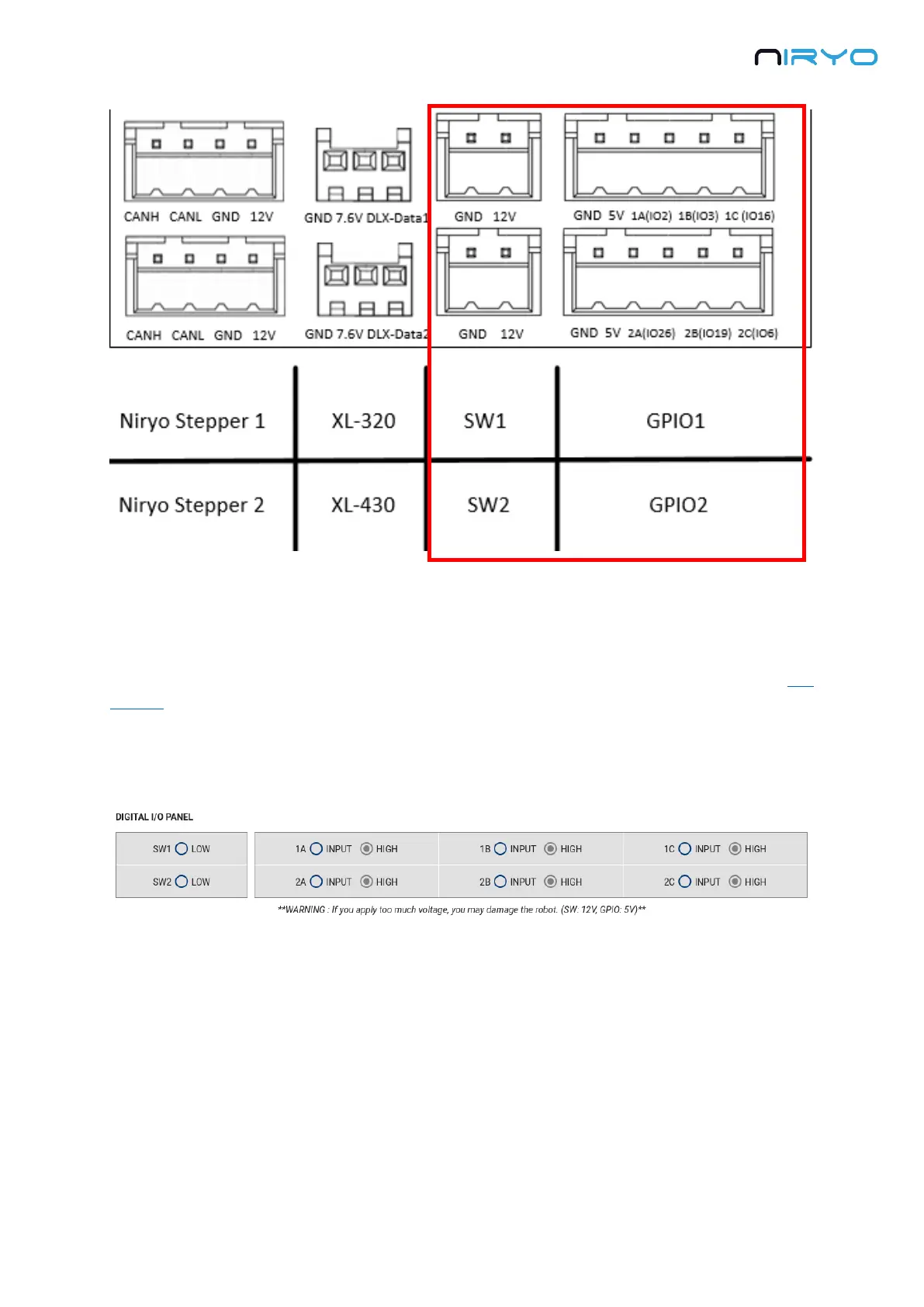
“SW1” and “SW2” connector can be used to plug a fan, a motor, etc.
For “GPIO1” and “GPIO2”, you have, from left to right: GND, 5V, and 3 digital pins. The digital
pins can be used to communicate with another device (ex: an Arduino board. Check out this
tutorial to learn more about that).
In Niryo One Studio → “Digital I/O panel” section, you can control the 2 switches and all 6
digital pins.
The switches are already set as OUTPUT mode and cannot be changed. You can
activate the 12V output (HIGH) or deactivate it (LOW).
A digital pin (GPIO) can be set as an INPUT or OUTPUT mode. When in INPUT mode, you
can read the state of the pin (LOW or HIGH). When in OUTPUT mode, you can set the state of
the pin (LOW or HIGH).
By default, all the digital pins are set to INPUT mode, HIGH state.