7
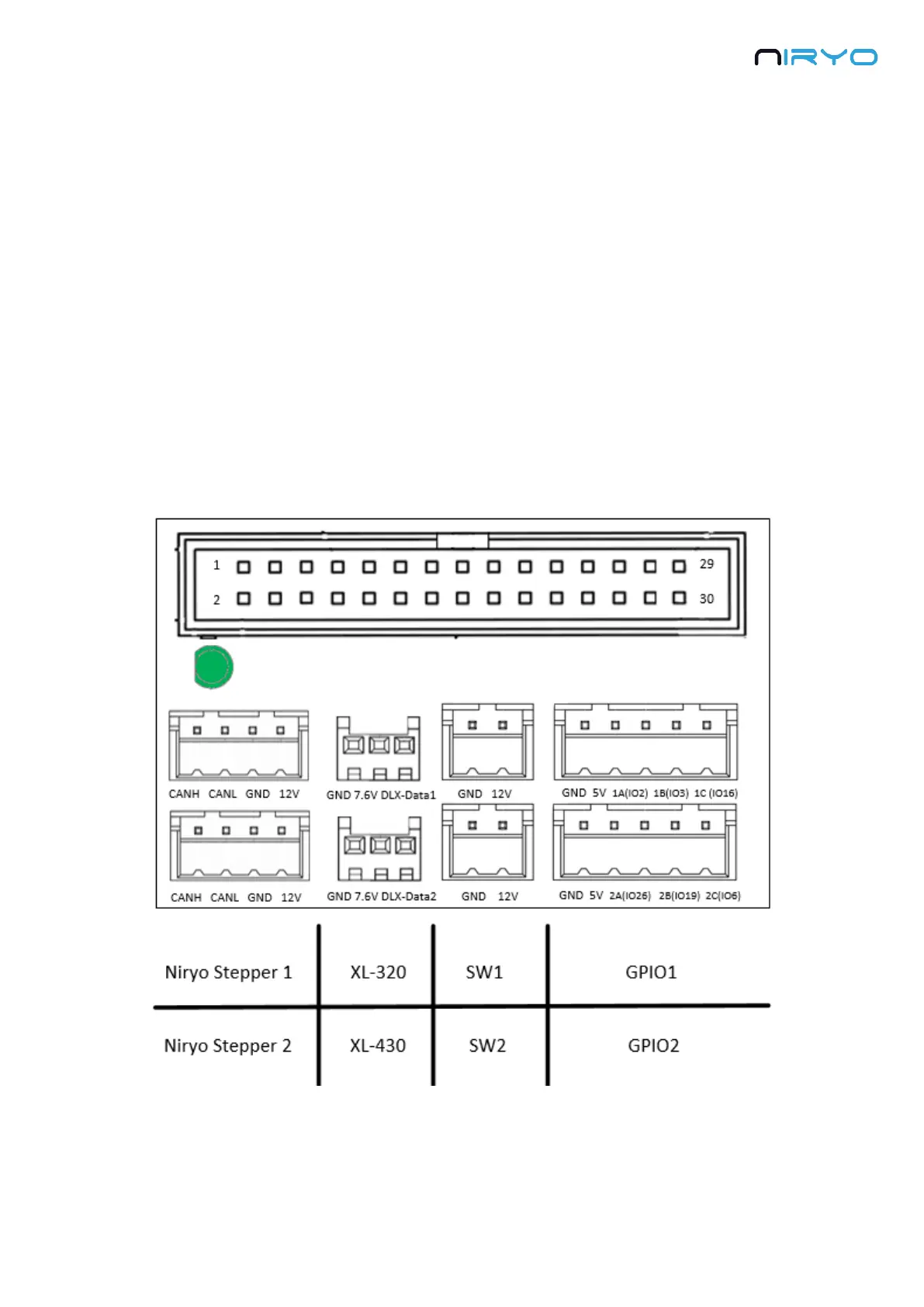
9. GPIO panel * 2. Total 6 digital pins, actionable through software. You can use GPIO1 and
GPIO2 pins as 5V digital pins (mode: input or output, state: high or low).
10. Power switch
11. Power adapter connector
⚠ Ensure your power adapter has a 12V output and is able to provide 6A. Lower output
voltage and current may cause the robot to fail to move correctly. Higher output voltage and
current may permanently damage the robot, and can be a cause of fire.
2.2 Panel connector
Here is a more detailed view of the panel connector:
⚠ Electrical rules and warnings for the panel connector: