NSW-5
Tuning and Flashing Instructions
PAMS Technical Documentation
Page 12
Issue 1 10/00
E 2000 Nokia Mobile Phones Ltd.
– Settings for pulse power meter:
SCalibrate if necessary
SCorrect frequency
SRef LVL offset and –>Attenuation to EXT Antenna con-
nector
SCorrect duty cycle: 33.3 % in digital mode and 100% in
analog mode
– Select Tuning –>Using WinTesla Select Tuning –> TX Power –>LOW
BAND / HIGH BAND –> EEPROM values
– All power channel have to be tuned. Repeat this test for A, B, C and D
power channel. The Power channel change reads old tuning values
from phone’s EEPROM.
– Adjust the power level by clicking the + and – buttons, and change lev-
els with keyboard ↑ and ↓ keys.
– Tune power levels which are shown by ”# for calculate”.
– Press Calculate button to calculate all other power levels.
– Check tuning of intermediate power levels. Do Fine tuning if neces-
sary.
– Once all TX levels are correct, press SAVE button.
– Tuning is successful if both Analog mode and 800 MHz and 1900MHz
digital mode are tuned.
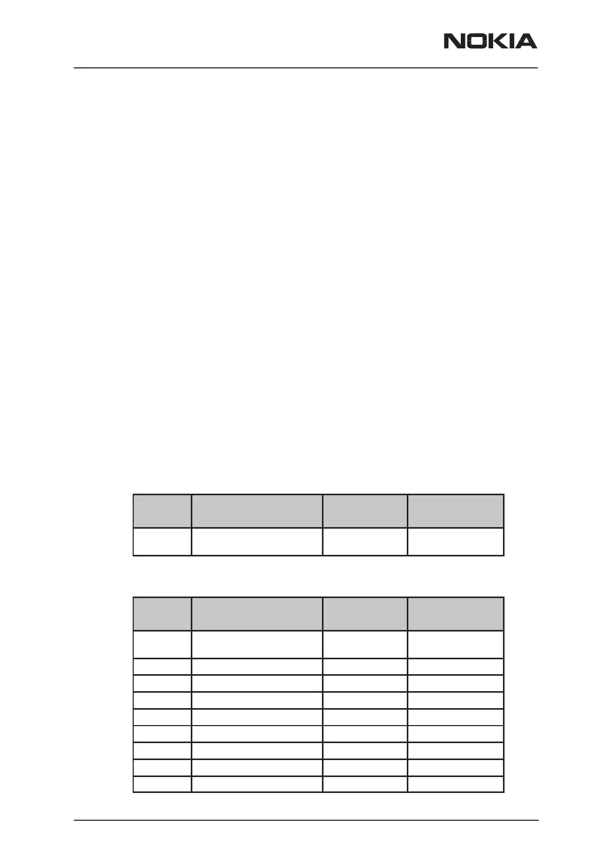
800MHz Analog TX output power
Power
level
RF Power at ext. RF
connector (*
Tuning target
tolerance
Testing Limits
2 24.5 dBm +/– 0.1 dB +0.5…– 0.5 dB
25.0 – 24.0 dBm
800MHz Digital TX output power
Power
level
RF Power at ext. RF
connector (*
Tuning target
tolerance
Testing Limits
2 26.8 dBm +/– 0.1 dB +0.5...–1.0 dB
27.3 – 25.8 dBm
3 23.5 dBm +/– 1.0dB +/– 2.0 dB
4 19.8 dBm +/– 1.0dB +/– 2.0 dB
5 15.8 dBm +/– 1.0dB +/– 2.0 dB
6 11.8 dBm +/– 1.0dB +/– 2.0 dB
7 7.8 dBm +/– 1.0dB +/– 2.0 dB
8 3.8 dBm +/– 1.0dB +/– 2.0 dB
9 –0.2 dBm +/– 1.0dB +/– 2.0 dB
10 –3.8 dBm +/– 1.0dB +/– 2.0 dB
 Loading...


