NSW-5
Disassembly and Troubleshooting Instructions
PAMS Technical Documentation
Page 31
Issue 1 10/00
Nokia Mobile Phones Ltd.
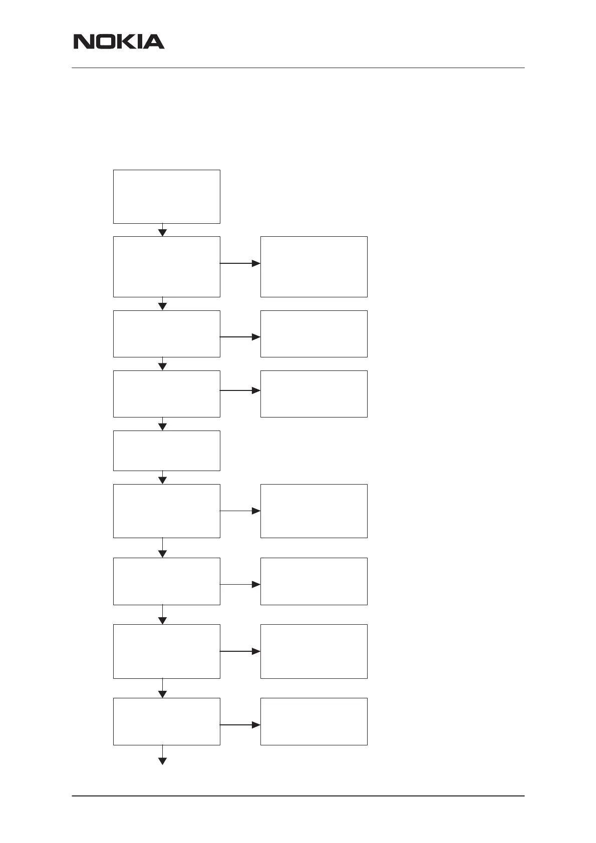
Troubleshooting charts for the receiver chain
AMPS RX
Apply 879.00 MHz (Ch 300)
–116 dBm , 8kHz dev,
1 kHz sine signal
(FM modulation)
to external antenna
connector (X991)
Check 3 multiplier output
level ( 58.32 MHz )
from coil L762
P:
≅
–10
…–20 dBm
N
N
Check level
from duplex filter
(Z910) input
P:
≅
–50 dBm
Check level
from frontend (N701)
LNA input pin no.7
P:
≅
–50 dBm
Check level
from LNA output
(N701) pin no.10
P:
≅
–30 dBm
Connect EXT HS to
audioanalyzator.
Open audio
AF: 1 kHz sine signal,
meas SINAD
SINAD: > 12 dB
Check UHF VCO
control voltage from
capasitor C831
V: 1.0
…4.0 V
AMPS
RX–chain OK
Y
N
N
Y
N
Change diplexer Z970
Note!
Check all soldering and
Components in antenna
circuit before changing
N
Y
Y
Change duplex filter Z910
or coil L701
Note!
Check all soldering and
discrete components of
frontend.
Change frontend N701
Y
Note!
AGC2 is on
= gain is in high state
(~2.8V at N701 pin no.9)
Check level from MXR
input (N701) pin no.12
P:
≅
0–2 dB less than at LNA
output pin no.10
Change RX bandfilter Z701
Note!
Check all soldering
N
Y
N
Y
Apply 879.00 MHz
–50dBm , carrier signal
(no modulation)
to external ant. connector
Start synthesizer
troubleshooting
Start synthesizer
troubleshooting
Note!
Signal level
 Loading...


