NSW-5
Disassembly and Troubleshooting Instructions
PAMS Technical Documentation
Page 22
Issue 1 10/00
Nokia Mobile Phones Ltd.
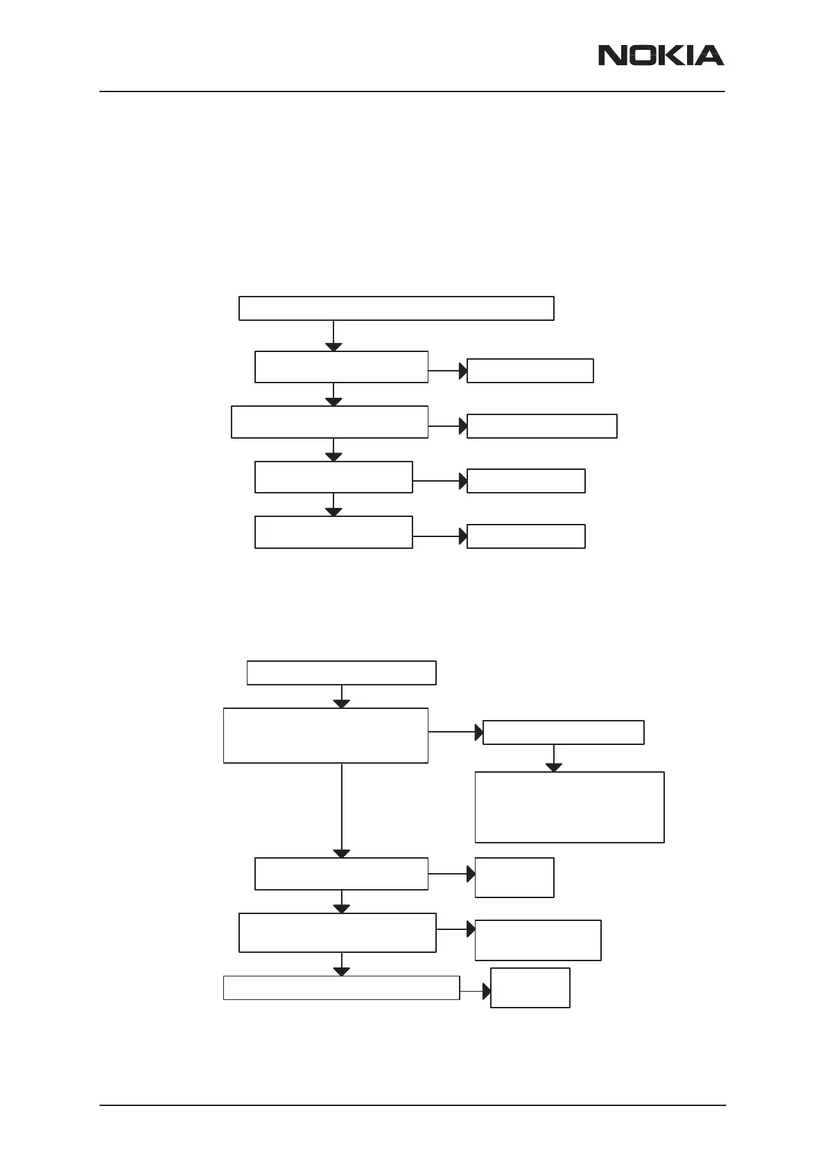
5. Audio Failure
In this kind of fault, it is useful to check first that slide rails and the rail
connector are OK.
Uplink (microphone) and downlink (speaker) are disfunctional
Voltage at C278 is 2.8 V HOOKINT
(without external audio devices)
Voltage at C271 is 2.8 V HEADSETINT
(without external audio devices)
Frequency at J255 is 1 MHz
square wave 2.8 Vpp
Frequency at J256 is 8 kHz
square wave pulses 2.8 Vpp
Check R260 and R270
Check R268, R265 and R260
Check N250 (Cobba)
Check N250 (Cobba)
YES
NO
YES
YES
YES
NO
NO
NO
If the downlink is broken, check that speaker is OK; ie. the grey metal
parts are not sticking out of the black plastic causing short circuits on the
speaker pads, or the membrane broken.
Uplink (microphone) is disfunctional
MICP voltage at pin 5 of V252 is 1.8 V
MICN voltage at pin 4 of V252
(J100) is 0.3 V during a call
NO
YES
Check microphone and micbias
components V250, V252, R259,
C286 and R275
If OK, check that VR1_sw is 2.7 V
during a call (R259)
YES
DC voltage at V252 pins 1 and 3
is 1.4 V during a call
NO
Check
N250 (Cobba)
YES
Analog audio signal (a few millivolts)
at V252 pins 1 and 3 during a call
NO
Check C256, C285
and PWB routings
YES
Check
N250 (Cobba)
Digital PCM data at J253 during a call
NO
Check slide and slide connector
OK
Figure 4. Troubleshooting diagrams for Audio failure
 Loading...


