NSW-5
System Module UT5U
PAMS Technical Documentation
Page 8
Issue 1 10/00
Nokia Mobile Phones Ltd.
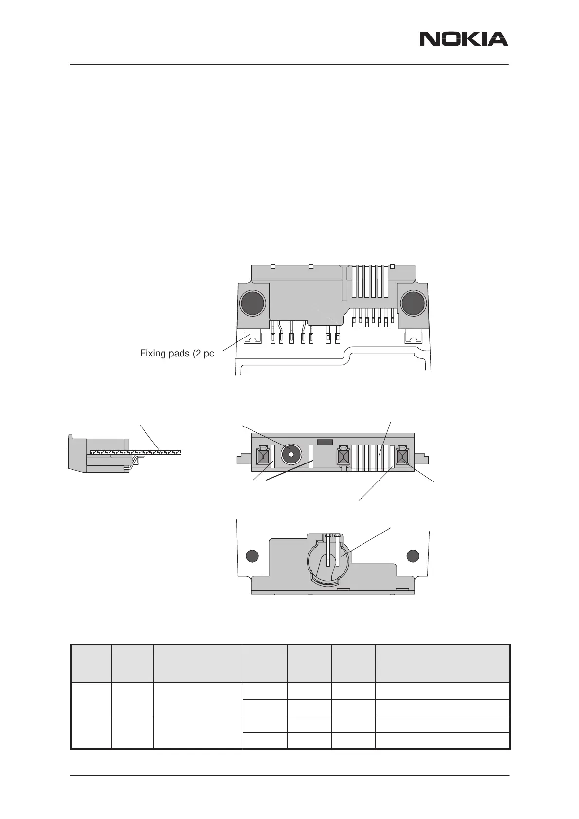
System Connector
The System connector provides
– 9 contact pads
2 for charging (Charge Voltage and Charging Control (PWM) )
6 for accessory interface
common GND
– 3–pole round DC–jack for charging
– Cavity and 2 contact springs for Slide Sensor Switch
The System Connector diagrams are below:
B side view
DC Jack
Cable locking holes (3 pcs)
Charger pads (2 pcs)
Accessory
connector (6 pads)
Engine PWB
Fixing pads (2 pcs)
A side view
Cavity and contact springs for
1
7
8
14
Common GND pad
Slide Sensor Switch
The System connector pin and signal listing is in the next table:
Con-
tact
pin
Line
Sym-
bol
Parameter Mini-
mum
Typical
/ Nomi-
nal
Maxi-
mum
Unit / Notes
1 VIN Charger input
6.0 V/ Unloaded ACP-8 Charger
voltage
650 mA/ Supply current
VIN Charger input
7.24 7.6 7.95 V/ Unloaded ACP–7 Charger
current
320 370 420 mA/ Supply current
 Loading...


