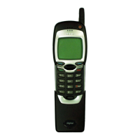
NSW-5
Disassembly and Troubleshooting Instructions
PAMS Technical Documentation
Page 51
Issue 1 10/00
Nokia Mobile Phones Ltd.
RF ASICs
General lnformation
EROTUS (N750) provides three main RF functions:
1. RX/TX IF blocks
2. PLLs for VHF and 1 GHz UHF
3. TX Power control circuits
The receiver block consists of IF buffers, active mixers, 6–multiplier
(3*+2*), AGC amplifier and limiter.
The transmitter section includes a digital gain step amplifier, a linear gain
control amplifier, a divider, an I/Q Modulator and control part for the
Transmitter Power Control loop.
The PLL section is controlled via the serial bus and contains both 1GHz
UHF and VHF PLLs and prescalers.
EROTUS
The EROTUS ASIC is in a TQFP64 type package, so RF probing for the
most signals is possible at the EROTUS pins. Signals can also be
checked at the components, which the signals are connected to.
Receiver front ends N701, N721
Pin no. Pin name Nominal level Description
1 LO IN 0 dBm N701
–4 dBm N721
Mixer LO input
2 Vdd buf 2.8V TX LO–buffer Vdd
3 LO out –3 dBm N701
–3 dBm N721
TX LO–buffer output
4 GND 0 Ground
5 Vdd LNA 2.8V LNA Vdd
6 GND 0 Ground
7 LNA in – LNA RF input port
8 GND 0 LNA ground
9 Gain Sel > 2 V High Gain
< 0.5 V Low Gain
LNA gain select
10 LNA out – LNA output port
11 GND 0 Ground
12 Mxr RF – Mixer RF input port
13 GND/IF 0 Ground (–IF tuning in N721)
14 MXR IF – Mixer IF output port

 Loading...