NSW-5
Disassembly and Troubleshooting Instructions
PAMS Technical Documentation
Page 34
Issue 1 10/00
Nokia Mobile Phones Ltd.
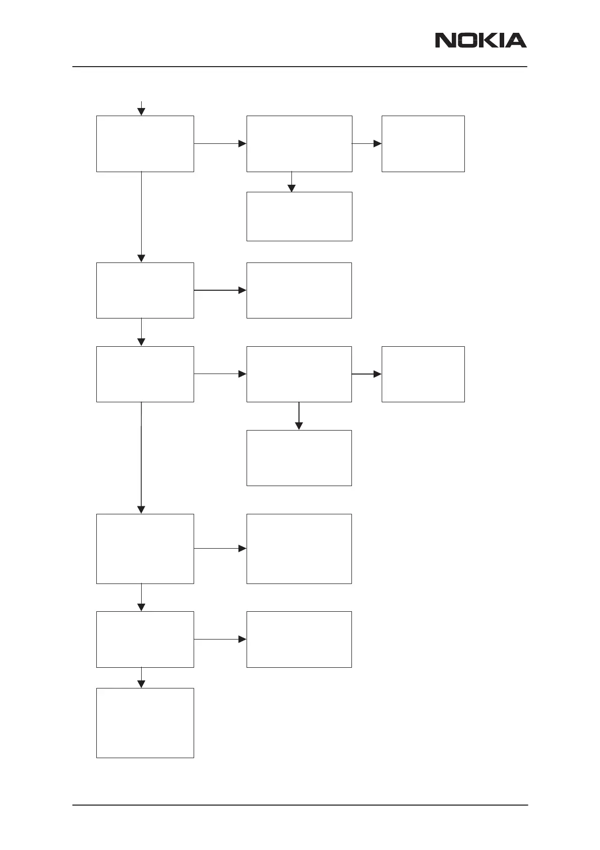
Check input level of
buffer (450 kHz) from
capasitor C768
P:
≅
about 6 dB less
than at C770
(IF2–filters input level)
Change IF2–filter(s)
Z750 and/or Z751
Check output level of
buffer from
resistor R798
P:
≅
–13 dBm
Note !
Check comp. R765 & C770
Check input level of
EROTUS IF amplifier
(116.19 MHz)
from resistor R744
P:
≅
–35 dBm
Change IF1–filter Z741
Note!
Check all components around filter
N
Y
N
Y
N
Y
Check input level of
IF2–filters (450 kHz) from
capasitor C770
P:
≅
–36 dBm
Change
EROTUS
N750
N
Note !
Check components and
voltages around EROTUS
and also AGC1 line
Y
Change
EROTUS
N750
Note !
Check comp. R798, C750 &
C751 and also check voltages
around EROTUS
TDMA 800
RX–chain is OK.
Start baseband
troubleshooting
(signal go next to
COBBA IC N250)
Check level of IF1 signal
(116.19 MHz) from MXR
output (N701) pin no.14
P:
≅
–29 dBm
Check level of LO signal
(995.19 MHz) from LO
input (N701) pin no.1
P: > –3 dBm
Note!
Check all components
around N701
N
Y
Change frontend N701
Y
N
Start synthesizer
troubleshooting
Y
Check level of OSC–sinal
(19.44 MHz) from
EROTUS (N750) pin no.24
P:
≅
+3 dBm
Start synthesizer
troubleshooting
Y
N
 Loading...


