10
1
17
16
20
24
23
18
19
22
21
26
25
29
27
28
30
31
3
2
4
5
10
12
14
13
11
15
6
7
9
8
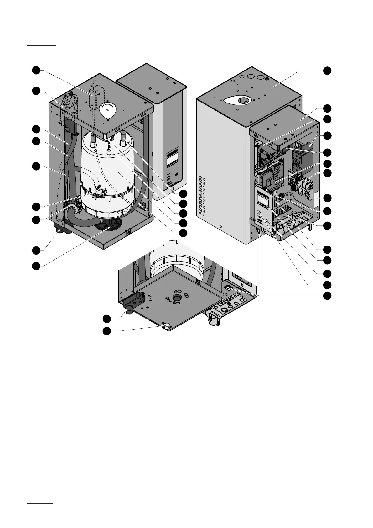
3.3 Steam generator construction
1 Steam cylinder compartment (small, medium, large)
2 Control compartment
3 Power board
4 Main contactor
5 Transformer
6 Steam bath board
7 Connecting terminals
8 Type plate
9 Remote operating and fault indication board (option)
10 Cable openings
11 Control board with CF Card
12 Display and control unit
13 Drain key
14 Operation status indicators
15 Unit switch
16 SC pump
17 Water cup
18 Filling and draining hose
19 Water supply hose
20 Overow hose
21 Inlet valve
22 Drain pump
23 Drain cup
24 Steam cylinder receptacle
25 Drain hose (manual drain)
26 Steam cylinder
27 Level sensor
28 Steam outlet
29 Electrode plug
30 Drain connector
31 Water supply connector
gure shows medium unit