System Setup
2-9
Part 1612500−02
E 2018 Nordson Corporation
To provide air to your system, an input air kit with connectors, couplings,
and 10-mm air tubing (15-ft for dolly systems, 25-ft for rail mount systems)
is available.
Refer to the Parts section for filter kits, replacement elements, and input air
kit part numbers and ordering information.
Mobile Systems
Connect 10-mm air tubing from your compressed air supply to the air input
fitting on the rear panel of the dolly.
Rail Mount Systems
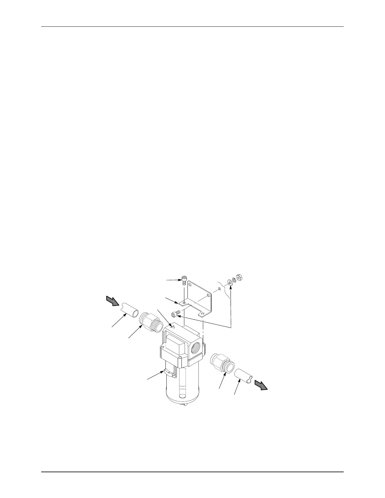
See Figure 3-9.
1. Use the mounting bracket (4) as a template to mark and drill mounting
holes in the selected mounting surface. Make sure there is sufficient
clearance to connect air tubing and change the filter element.
2. Install the two male connectors (2) included in the kit in the filter input
and output ports.
3. Install the mounting bracket on the filter, using the included M5 screws
(3), on the side of the filter opposite the release latch (6).
4. Mount the filter with customer-supplied fasteners (7).
5. Note the orientation of the flow indicator (5) on the top of the filter. Cut
10-mm blue air tubing to the required lengths to connect the air supply
to the filter and the filter to the controller, then connect the tubing.
1
1
2
2
3
4
6
5
7
FROM SUPPLY
TO CONTROLLER
Figure 2-9 Air Filter Installation − Wall and Rail Mount Systems
1. 10-mm air tubing (blue)
2. 10-mm tube x 1/2 male connectors
3. M5 screws
4. Bracket
5. Flow indicator
6. Release latch
7. Customer-supplied fasteners

 Loading...
