14Copyright©2016NortekSecurity&Control
Installation
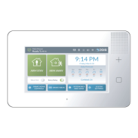
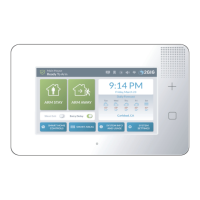
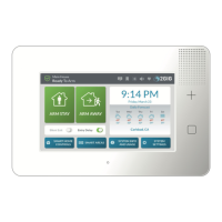
Control Panel Mounting Plate
MounttheControlPanelonthewallinacon venientlocation(orusetheoptionaldeskmount).Thesetoolsmayberequired
tomounttheControlPanelontothewall:
•Screwdriver
•WireStripper
•StapleGun
•DrywallSaw(orequivalent)
•Ladder
1 RemovethelockingscrewfromthetopoftheControlPanelcaseandremovethemountingplate.
2 Usethemountingplateasatemplatetomarkthewallforthewiringcutoutslot.Useadrywallsawtocuttheslot.
3 IfusingtheoptionalGSM(Cellular)RadioModulewithanexternalantenna,removetheplasticknockoutlabeled
“EXTERNALANTENNA”onthemountingplate.Markandcutaslotinthedrywallfortheexternalantenna.
4 Attachthemountingplatetothewallusingthree(3)screws.
Figure 5 Control Panel Mounting Plate
Wireless Sensors
InstallwirelesssensorsintheappropriatelocationusingtheInstallationInstructionsincludedwitheachwirelesssensorasa
guide.
Hardwired Loops
HardwiredloopscanbeprogrammedeitherNormallyOpen(N/O)orNormallyClosed(N/C).End‐of‐LineResistors(EOLR)
canalsobeusedtosupervisetheloops.Onlycontactsshouldbeusedwiththehardwiredloops.
NOTE: TheControlPaneldoesnotsupportpoweringexternaldevices(PIR’s,etc.).
NOTE: HardwiredloopscannotbeusedforaCOorFiresensorloop.
1 Ifeitherofthetwo(2)hardwiredloopsaregoingtobeused,installthecontactsandthenroutetheloopwiretothe
ControlPanel’ swallcutout.
2 Ifend‐of‐linesupervisionisrequiredfortheloop,installa2.2kΩresistor(notsupplied)asshowninFigure6Hardwired
LoopWiring.
A Mountingplate
B Removecasescrewandmountingplate
C Ifusingexternalantenna,removeknockoutplate.
D Usemountingplateasatemplatetomarkwirecutoutholeindrywall.
E Mountplatewiththree(3)screws.
 Loading...