ID50 Series Panel - Installation, Commissioning & Configuration Manual
Appendix 1 - Specifications
A1 - 4997-263, Issue 4
September 2002
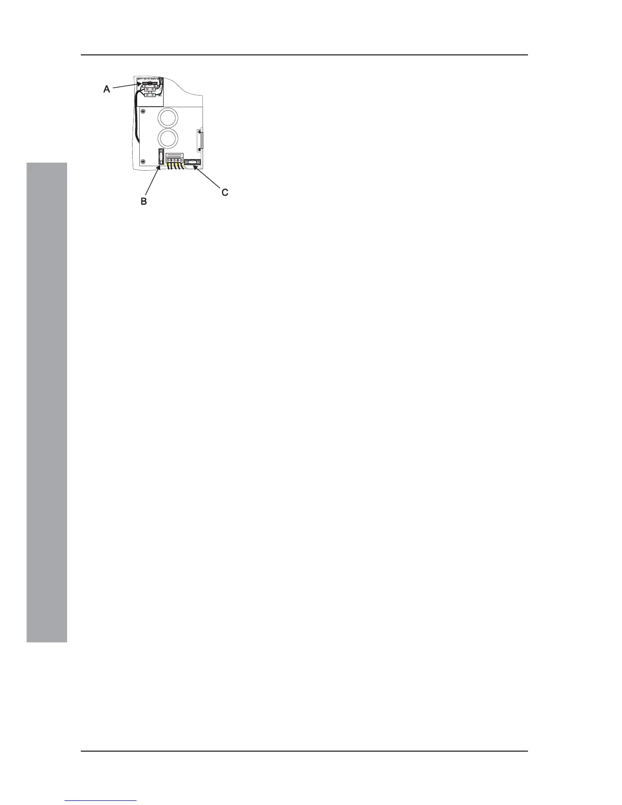
Fuses:
The location of the panel fuses is given here, together with their
ratings and their type.
a. MF1 Mains Supply T 2A 250V H
b. FS1 Transformer T 5A 250V H
c. FS2 Battery T 5A 250V H
T = time delay (i.e. anti-surge), H = high break capacity, as
defined by EN60127.
Outputs:
a. Two dedicated Sounder Outputs.
b. Two Sounder or Volt-free Contact (VFC) - selectable
outputs.
c. Two -VE Outputs (RLY) - unselectable outputs.
d. One loop output.
e. One DC auxiliary output.
Sounder Output Rating
Type: Voltage reversal.
Output voltage: 26 to 28V when active;
-6.8Vto-9Vwhen inactive.
Maximum load: 1A Total (max.700mA per output).
Fuse rating: Not applicable.
Monitoring: Open- and short-circuit.
Volt-free Contact (VFC) Output Rating
Type: Single-pole change-over
Maximum load: Contacts rated 30V 1A
Fuse rating: Not applicable
Switched -VE Output Rating
Output voltage: 21 to 30V
Maximum load: 83mA (total for both outputs)
Loop Output
Output voltage: 22.5 to 26.4V.
Maximum load: 0.5A peak current*
Max. loop impedance: 20 ohms (-ve cable only, with
duplicate address detection) or
40 ohms (-ve cable only, without
duplicate address detection).
Max. loop capacitance: 0.5mF
Up to 198 loop devices (up to 99 sensors and 99 modules) may
be fitted to the analogue loop.
The communication with devices on the loop uses the Notifier
CLIP protocol. Refer to Hardware Recommendations for a
list of compatible devices and loading limitations.