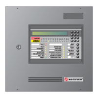
ID50 Series Panel - Installation, Commissioning & Configuration Manual
Appendix 1 - Specifications
A1 - 5 997-263, Issue 4
September 2002
DC Auxiliary Rating
Output voltage range: 26 to 28V
Maximum load:
Quiescent: 150mA*
Alarm: 0.25A*
Cables should be capable of
carrying a minimum 1A.
Fuse rating: Not applicable
Note: It is recommended that the auxiliary output
should not be used in the quiescent state other
than to provide a supply to drive ancillary devices
power indicators.
RS485 Serial Port (Optional)
Isolation: Functional at 30V.
Baud rate: 1200 Baud.
Connector: Terminal block on RS485 Interface
Module PCB.
Maximum cable length: 1200metres (minimum of 1.5mm
2
screened cable recommended)
Configuring
Configuration methods: Front panel keypad.
Offline using PC Offline Support
Tool program.
Configuration access: Keypad access is passcode-
protected (user-definable) for all
configuration.
Refer to Sections 4 & 5 of this
manual, and to 997-264 ID50
Series Panel Operating Manual,
Section4 for further information.
Default Configuration Passcodes:
Level 2 Passcode 2 2 2 2
Level 3 Passcode 3 3 3 3
Repeaters/Mimics
Refer to 997-411, IDR-2A, 2P & 6A Repeaters User
Manual and 997-412, IDR Mimic Installation and
Commissioning Manual for the specification.
* Total system load is limited by the
transformer output. The Notifier Loop
and Battery Calculator Support Tool,
should be used to ensure that the system
is NOT overloaded.
 Loading...


