2. Program Change How to Use the Basic Program
24
NFS-640 Programming Manual P/N 51333:B 10/03/2003
How to Modify an Addressable Control Module Point
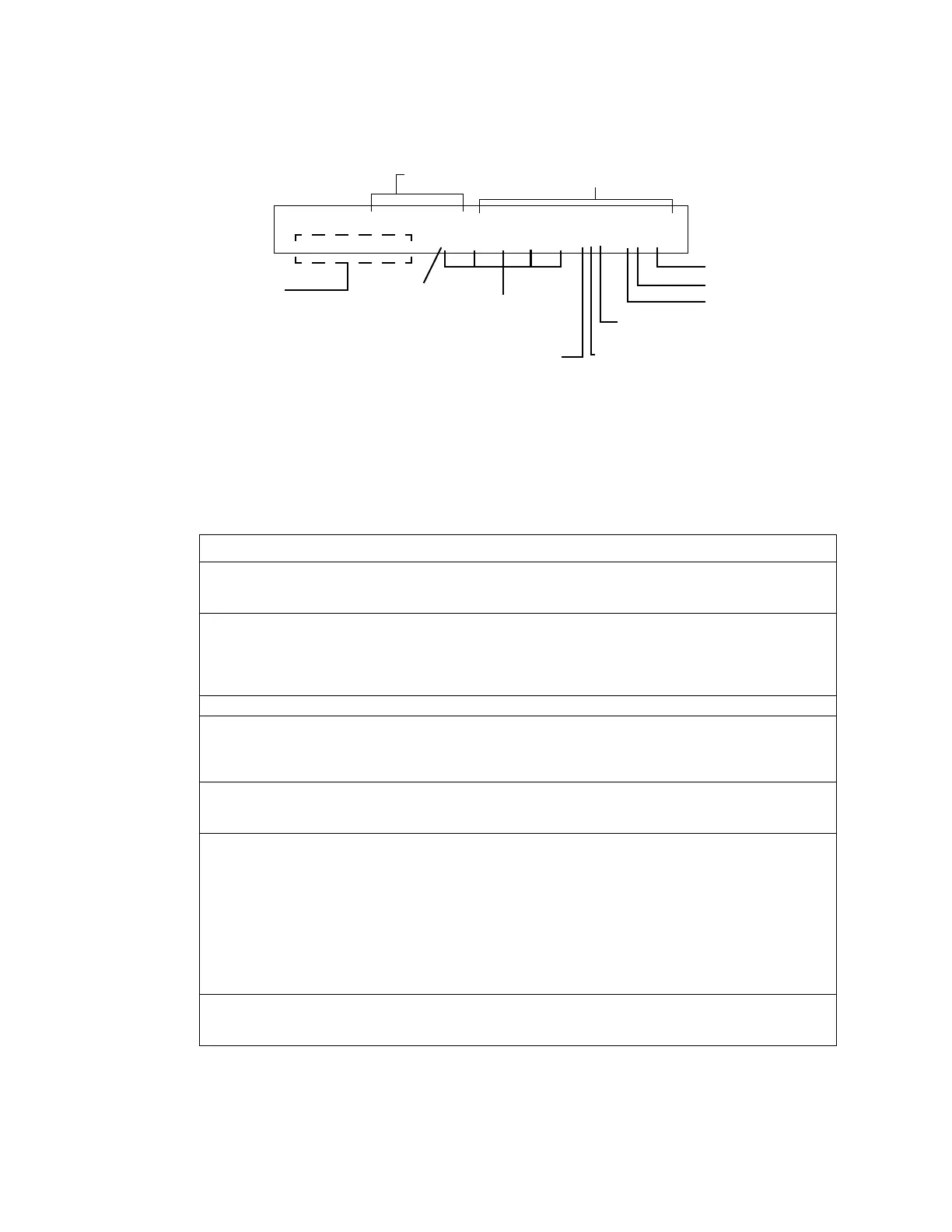
When you select a point address for modification, the control panel returns a screen that displays
information about the point. For example, the illustration below shows sample information for a control
module (2M101) in the LCD display.
To modify a point, follow these steps:
Note: A blinking cursor indicates the selected field.
1. From the programming screen, use the arrow keys to move to a field that you want to modify. See
below for descriptions and settings.
Table 7 Modifying Control Module Programming Selections
2. When finished modifying a point, press the
ENTER key; then press the NEXT or PREVIOUS key to
select another point.
Field Description Set as follows:
Type Code Specifies the function of the control module Press the NEXT or PREVIOUS Selection keys to scroll
through valid control module Type Code selections (listed
in Table 34 on page 106)
Custom Label 20 character custom label. Change by placing the cursor into the first space of the field
using the arrow keys, then typing the descriptor.
Note: Spaces must be input by the user, including any space
necessary between the custom and extended label fields. An
80-column printout will run the two fields together.
Extended Label 12 character custom label extension. See “Custom Label” above.
CBE list Up to five software zones can be entered to
define the output responses of the control
module based on various initiating
conditions (events)
Type the number of up to five zones, including E0-E9, F0-
F9, L0-L9, R0-R9, and zones 00-99. The first zone default
is Z00 (general alarm).
Switch Inhibit Specifies if an operator can manually
activate an output
Type one of the following entries.
I = Switch Inhibit enabled
* = no switch inhibit (default for all but releasing circuits)
Silenceable Specifies if an operator can manually silence
an activated output
Type one of the following entries.
* = output nonsilenceable
F = silenceable, resound by fire alarm
U = silenceable, resound by supervisory alarm
B = silenceable, resound by security alarm
T = silenceable, resound by trouble
O = silenceable, does not resound
Note: If the “Strobe” Type ID is used with System Sensor
Strobe synchronization, F, U, B, T, or O will silence the
entire circuit, “*” will silence the horn portion only.
Walk Test Specifies if outputs sound during Walk Test Type one of the following entries.
W = devices sound (Basic Walk Test)
* = devices do not sound (Silent Walk Test) (default)
Walk Test Selection: *=off
(default); W=selected
Silenceable: S=selected; *=off (default)
Note: On a control module, the default zone
is always set to Zone 00 (general alarm).
Default zone
Blinking Type Code selection
CBE list
(five zones)
12 spaces for extended
custom label
SLC number (1 or 2)
M (module)
SLC address (001-159)
Switch Inhibit: I=selected; *=off (default)
PROGRAM CONTROL MODULE CONTROL 2M101
00 __ __ __ __ ISW 2M101
20-character user-editable custom label
www.PDF-Zoo.com

 Loading...


